Radio modem RipEX is best suited for transmission of a large number of short messages where a guaranteed delivery is required, i.e. for mission critical applications.
RipEX has the following basic uses:
Polling
In poll-response networks a central master unit communicates with a number of remote radiomodems one at a time. The master unit exchanges data with the currently connected remote radio, and when finished, it establishes a new connection with the next remote radio according to the polling order.Report-by-exception
In report-by-exception networks remote units can be contacted similarly to polling networks. In addition, any remote unit can spontaneously send data to the master unit (typically an alarm).Mesh
In mesh type networks any radio modem in the network can access any other radio modem randomly and spontaneously. Mesh network can also host polling or report-by-exception applications, even in several instances.
To be able to satisfy different types of applications, RipEX offers multiple options for building a radio network. There are 2 different Operation modes, Bridge and Router with 3 different protocols on Radio channel:
Transparent used in Bridge mode
Flexible used in Router mode
Base driven used in Router mode
Bridge mode with fully transparent Radio protocol is suitable for all polling (request-response) applications with star network topologies, however repeater(s) are possible.
A packet received through any interface is broadcast to the appropriate interfaces of all units within the network. Packets received on COM are broadcast to both COM1 and COM2 at remote sites, allowing you to connect 2 RTUs to any radio modem.
Any unit can be configured as a repeater. A repeater relays all packets it receives through the radio channel. The network implements safety mechanisms which prevent cyclic loops in the radio channel (e.g. when a repeater receives a packet from another repeater) or duplicate packets delivered to the user interface (e.g. when RipEX receives a packet directly and then from a repeater).
Beside standard packet termination by an “Idle” period on the serial port (a pause between received bytes) the bridge mode also offers “streaming”. While in streaming mode, transmission on the radio channel starts immediately, without waiting for the end of the received frame on COM => zero latency.
One of the advantages of the Bridge mode (together with Radio Transparent protocol) is its transparency. For example: both IPv4 and IPv6 type of traffic passes through; Frames defined by IEEE802.1Q-2018 are supported (e.g. VLAN, QinQ).
| Note | |
|---|---|
Limited broadcast 255.255.255.255 and Direct broadcast e.g. 192.168.255.255 as well as Multicast (224.0.0.0 through 239.255.255.255) on Ethernet are supported and transferred over the network. |
You can see an instructional video explaining the Bridge mode
functionality here:
https://www.racom.eu/ripex-bridge-mode
Bridge mode is suitable for Point-to-Multipoint networks, where Master-Slave applications with polling-type communication protocol are used. RipEX in bridge mode is as easy to use as a simple transparent device, while providing communication reliability and spectrum efficiency by employing a sophisticated protocol in the radio channel.
In bridge mode, the radio channel protocol does not solve collisions. There is a CRC check of data integrity, however, i.e. once a message is delivered, it is 100% error free.
All the messages received from user interfaces (ETH&COM) are immediately transmitted to the radio channel.
ETH – The whole network of RipEX radiomodems behaves as a standard Ethernet network bridge. Each ETH interface automatically learns which devices (MAC addresses) are located in the local LAN and which devices are accessible over the radio channel. Consequently, only the Ethernet frames addressed to remote devices are physically transmitted on the radio channel. This arrangement saves the precious RF spectrum from extra load which would be otherwise generated by local traffic in the LAN (the LAN to which the respective ETH interface is connected).
One has to be very careful when RipEX in Bridge mode is connected to LAN, because all LAN traffic is then broadcast to the Radio channel.
COM1,COM2 – All frames received from COM1(2) are broadcast over the radio channel and transmitted to all COM ports (COM1 as well as COM2) on all radio modems within the network, the other COM on the source RipEX excluding.
There is a special parameter TX delay (Adv. Config., Device), which should be used when all substations (RTU) reply to a broadcast query from the master station. In such case massive collisions would ensue because all substations (RTU) would reply at nearly the same time. To prevent such collision, TX delay should be set individually in each slave RipEX. The length of responding frame, the length of Radio protocol overhead, modulation rate have to be taken into account.
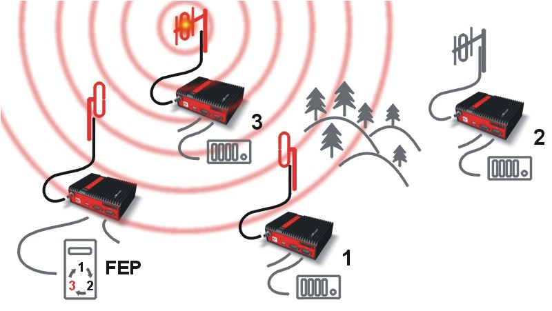
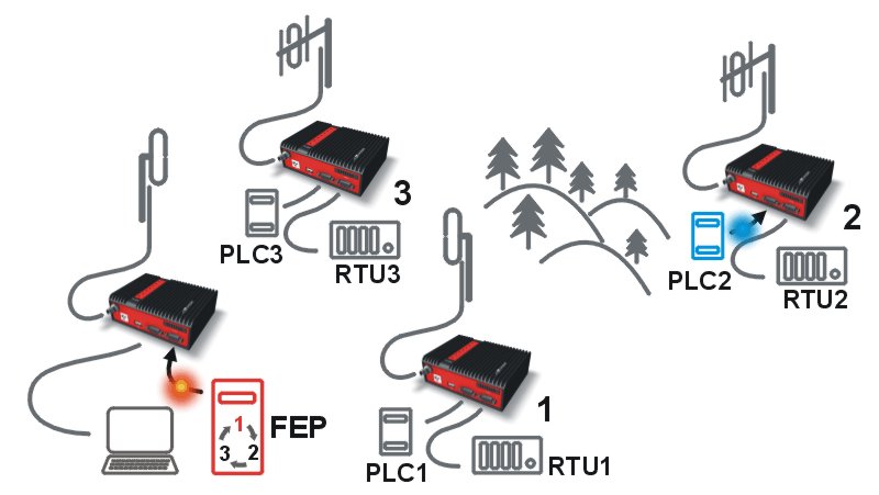
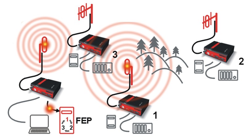
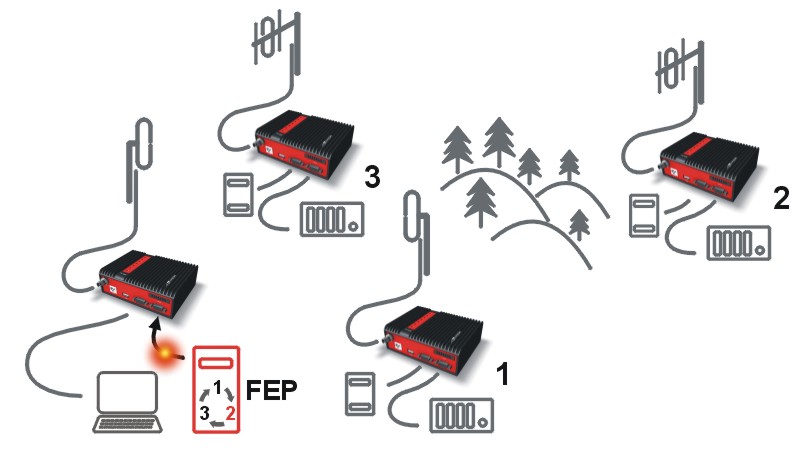
In the following, common acronyms from SCADA systems are used:
FEP – Front End Processor, designates the communication interface equipment in the centre
RTU – Remote Telemetry Unit, the terminal SCADA equipment at remote sites
The single digits in illustrations are “site names” and do not necessarily correspond with actual addresses of both the RipEX‘s and SCADA equipment. Address configuration examples are given in the next chapter.
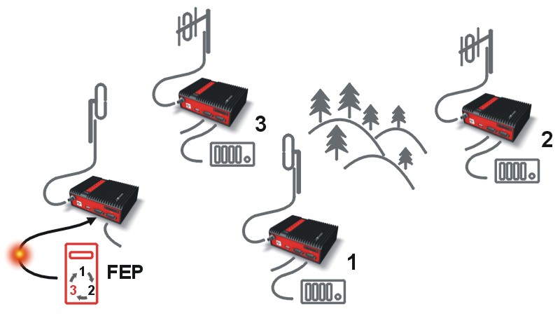 |
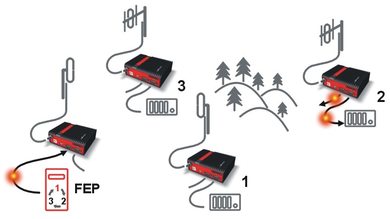
Step 1 Polling cycle starts: |
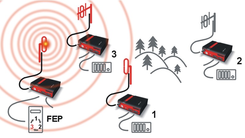 |
Step 2 FEP’s RipEX broadcasts this packet on Radio channel. |
 |
Step 3 RipEX 3 and RipEX 1 send the received packet to their COM1 and
COM2. |
 |
Step 4 RipEX 2 sends repeated packet to its COM1 and COM2. |
 |
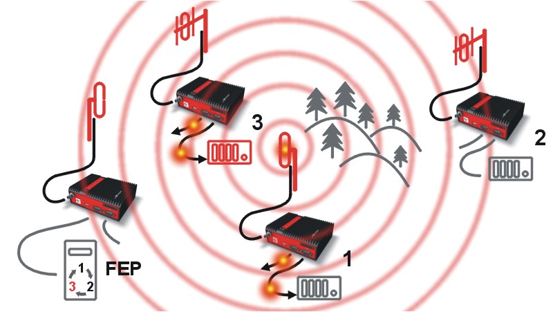
Step 5 RipEX 3 broadcasts the reply packet from RTU3 on Radio
channel. |
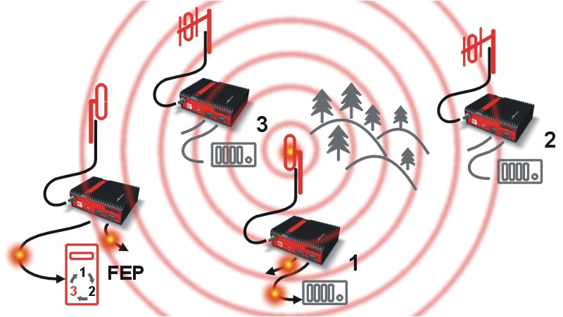 |
Step 6 FEP’s RipEX sends the packet (the reply from RTU3) to FEP through
COM1. |
 |
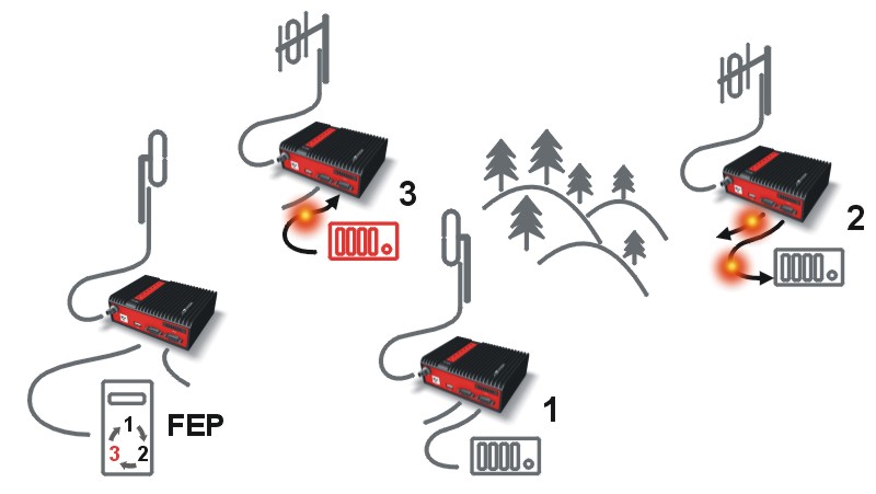
Step 7 RipEX 2 sends repeated packet to its COM1 and COM2. |
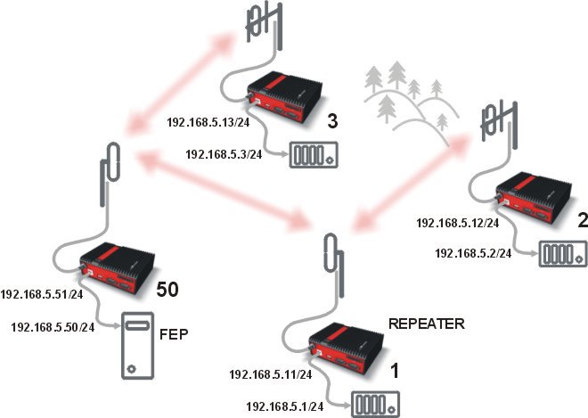
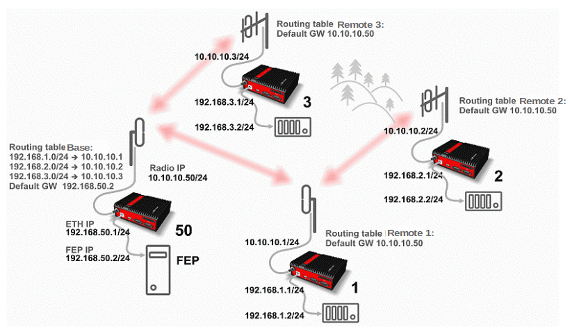
You can see an example of IP addresses of the SCADA equipment and RipEX‘s ETH interfaces in the picture below.
In Bridge mode, the IP address of the ETH interface of RipEX is not relevant for user data communication. However it is strongly recommended to assign a unique IP address to each RipEXs’ ETH interface, since it allows for easy local as well as remote service access. Moreover, leaving all RipEX‘s with the same (= default) IP on the ETH interface may cause serious problems, when more RipEX units are connected to the same LAN, even if by accident (e.g. during maintenance).
Repeater
Because using the bridge mode makes the network transparent, the use of repeaters has certain limitations. To keep matters simple we recommend using a single repeater. However, if certain rules are observed, using multiple repeaters in the same network is possible.
The total number of repeaters in the network is configured for every unit individually under Bridge mode parameters. This information is contained in every packet sent. All units that receive such packet will resume transmission only after sufficient time has been allowed for the packet to be repeated. The packets received from user ports remain buffered and are sent after the appropriate time passes. This prevents collisions between remote radio modems. There can be no repeater collisions if only one repeater is used.
Where two or more repeaters are used, collisions resulting from simultaneous reception of a repeated packet must be eliminated. Collisions happen because repeaters repeat packets immediately after reception, i.e. if two repeaters receive a packet from the centre, they both relay it at the same time. If there is a radiomodem which is within the range of both repeaters, it receives both repeated packets at the same time rendering them unreadable.
Examples:
1. Repeaters connected serially
 |
A packet is transmitted and repeated |
 |
In improperly designed networks collisions happen if a remote radio modem lies
in the range of two repeaters (see the image): the packet sent from the centre (1)
is received by both repeaters. It is repeated by them both (2) causing a collision
at the remote. In other words – there should not be more than one repeater where
the centre and remotes’ coverage areas overlap. |
 |
Solution 1. |
 |
Solution 2. |
2. Parallel repeaters
 |
Improperly designed network: – RipEX REM1 is within the range of two repeaters (RPT1 and RPT2). The repeaters receive a packet (1) from the centre (CEN) and repeat it at the same time (2) causing a collision at REM1.
Well-designed network: – A remote is only in the range of a single repeater (REM1-RPT1, REM2-RPT2).
|
RipEX works as a standard IP router with 2 independent interfaces: Radio and ETH. Each interface has its own MAC address, IP address and mask.
IP packets are processed according to routing table rules. You can also set the router’s default gateway (applies to both interfaces) in the routing table.
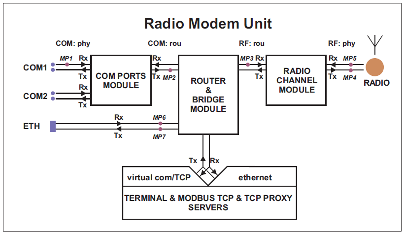
The COM ports are treated as standard host devices, messages can be delivered to them as UDP datagrams to selected port numbers. The destination IP address of a COM port is either the IP of ETH or the IP of a radio interface. The source IP address of outgoing packets from COM ports is always the IP of the ETH interface.
The additional Virtual COM ports and Terminal server can act as other IP router ports. This enables Serial and TCP based RTUs to be combined in one network.
Two different Radio protocols are available in the Router mode: Flexible and Base driven.
Flexible
Suitable for master or even multi master-slave polling and report by exception from remotes concurrently. No limits in network design – each radio can work as base station, a repeater, a remote, or all of these simultaneouslyBase driven
This protocol is optimized for TCP/IP traffic and/or ‘hidden’ Remotes in report-by-exception networks, when a Remote is not be heard by other Remotes and/or different Rx and Tx frequencies are used. It is suitable for a star network topology with up to 255 Remotes under one Base station, where each Remote can simultaneously work as a Repeater for one or more additional Remotes.
Router mode with Flexible protocol is suitable for Multipoint networks of all topologies with unlimited number of repeaters on the way, and all types of network traffic where Multi-master applications and any combination of simultaneous polling and/or report-by-exception protocols can be used
Each RipEX can access the Radio channel spontaneously using sophisticated algorithms to prevent collisions when transmitting to the Radio channel. Radio channel access is a proprietary combination of CSMA and TDMA; the Radio channel is deemed to be free when there is no noise, no interfering signals and no frames being transmitted by other RipEX stations. In this situation, a random selection of time slots follows and a frame is then transmitted on the Radio channel.
Frame acknowledgement, retransmissions and CRC check, guarantee data delivery and integrity even under harsh interference conditions on the Radio channel.
In the following example, there are two independent SCADA devices connected to RipEX‘s two COM ports. One is designated RTU (Remote Telemetry Unit) and is assumed to be polled from the centre by the FEP (Front End Processor). The other is labelled PLC (Programmable Logic Controller) and is assumed to communicate spontaneously with arbitrary chosen peer PLCs.
 |
Step 1 FEP sends a request packet for RTU1 through COM2 to its connected RipEX.
|
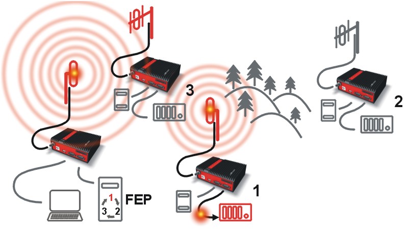 |
Step 2 FEP’s RipEX transmits an addressed packet for RTU1 on Radio channel.
|
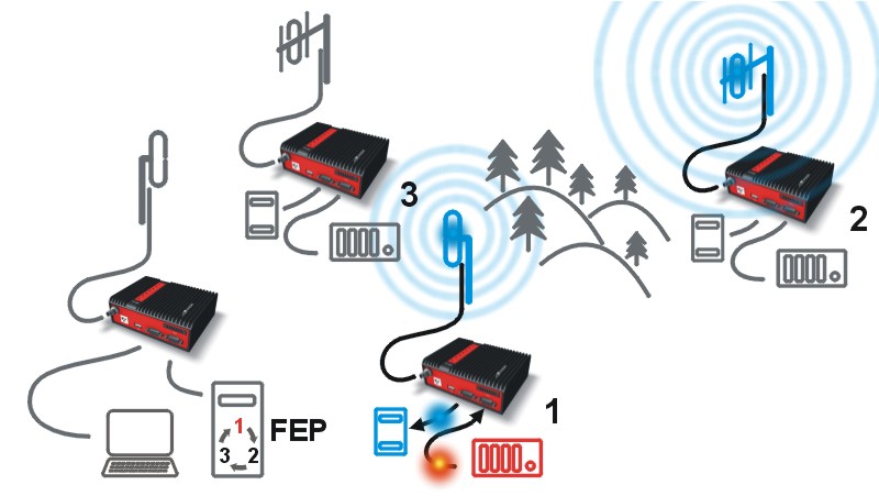 |
Step 3 RipEX 2 waits till previous transaction on Radio channel is finished
(anti-collision mechanism). |
 |
Step 4 RipEX 1 transmitts the reply packet from RTU1 for FEP on Radio channel.
|
 |
Step 5 FEP receives the response from RTU1 and polling cycle
continues… |
As it was mentioned above, RipEX radiomodem works as a standard IP router with two independent interfaces: radio and ETH. Each interface has got its own MAC address, IP address and mask.
The IP router operating principles stipulate that every unit can serve as a repeater.. Everything what is needed is the proper configuration of routing tables.
Radio IP addresses of the RipEX’s required to communicate over the radio channel must share the same IP network. We recommend planning your IP network so that every RipEX is connected to a separate sub-network over the Ethernet port. This helps to keep the routing tables clear and simple.
| Note | |
|---|---|
Even if the IP addresses of all RipEX units in a radio channel share a single IP network, they may not be communicating directly as in a common IP network. Only the RipEX units that are within the radio range of each other can communicate directly. When communication with radio IP addresses is required, routing tables must include even the routes that are within the same network (over repeaters), which is different from common IP networks. The example configuration below does not show such routing rules for the sake of simplicity (they are not needed in most cases). |
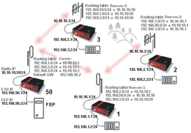
Formal consistency between the last byte of the radio IP address and the penultimate byte of the Ethernet address is not necessary but simplifies orientation. The “Addressing” image shows a routing table next to every RipEX. The routing table defines the next gateway for each IP destination. In radio transmission, the radio IP of the next radio-connected RipEX serves as the gateway.
Example of a route from FEP (RipEX 50) to RTU 2:
The destination address is 192.168.2.2
The routing table of the RipEX 50 contains this record:
Destination 192.168.2.0/24 Gateway 10.10.10.1Based on this record, all packets with addresses in the range from 192.168.2.1 to 192.168.2.254
are routed to 10.10.10.1Because RipEX 50’s radio IP is 10.10.10.50/24, the router can tell that the IP 10.10.10.1 belongs to the radio channel and sends the packet to that address over the radio channel
The packet is received by RipEX 1 with the address 10.10.10.1 where it enters the router
The routing table of RipEX 1 contains the record:
Destination 192.168.2.0/24 Gateway 10.10.10.2
based on which the packet is routed to 10.10.10.2 over the radio channelThe packet is received by RipEX 2
The router compares the destination IP 192.168.2.2 with its own Ethernet address 192.168.2.1/24
and determines that the packet’s destination is within its ETH network and sends the packet over the Ethernet interface – eventually, the packet is received by RTU 2.
In large and complex networks with numerous repeaters, individual routing tables may become long and difficult to comprehend. To keep the routing tables simple, the addressing scheme should follow the layout of the radio network.
More specifically, every group of IP addresses of devices (both RipEX‘s and SCADA), which is accessed via a repeater, should fall in a range which can be defined by a mask and no address defined by that mask exists in different part of the network.
A typical network consisting of a single centre and number of remotes has got a tree-like layout, which can be easily followed by the addressing scheme – see the example in the Figure “Optimised addressing” below.

The default gateway is also a very powerful routing tool, however be very careful whenever the default route would go to the radio interface, i.e. to the radio channel. If a packet to non-existing IP destination came to the router, it would be transmitted over the radio channel. Such packets increase the load of the network at least, cause excessive collisions, may end-up looping etc. Consequently the default route should always lead to the ETH interface, unless you are perfectly certain that a packet to non-existing destination IP may never appear (remember you are dealing with complex software written and configured by humans).
All traffic over the Radio channel is managed by the Base station. Radio channel access is granted by a deterministic algorithm resulting in collision free operation regardless of the network load. Uniform distribution of Radio channel capacity among all Remotes creates stable response times with minimum jitter in the network.
All communication on Radio channel is controlled by the Base station; all frames inside the radio network have to be routed through the Base station. Appropriate routing has to be set.
Base station can communicate with different Modulation data speeds and different FEC settings.
Any Remote can work as a Repeater for another Remote. Only one Repeater is possible between Base station and Remote, however a number of Remotes can use the same Repeater.
There is no need to set any routes in Routing table(s) for Remote stations located behind Repeater. Forwarding of frames from the Base station over the Repeater in either direction is serviced transparently by the Base driven protocol.
When Remote to Remote communication is required, respective routes via the Base station must be set in Routing tables in the Remotes.
Frame acknowledgement, retransmissions and CRC check, guarantee data delivery and integrity even under harsh interference conditions on the Radio channel.
A star topology with one repeater is used in the following example of a SCADA network using a polling and report by exception combination. The Repeater is also serving as a Remote radio. The packets’ acknowledgement on Radio channel is used for transmissions in both directions in the example
Step 1
Base RipEX regularly checks the queue status of remote RipEX radios
for which it has no queueing information. The feedback enables the Base station to manage
time allocations for all Remotes to transmit.
Step 2
FEP sends a request packet to RTU1 via Base RipEX; Base RipEX packet
transmits in shortest possible time. Remote RipEX 1 receives the packet and hands it over to
RTU1, simultaneously acknowledging packet receipt to the Base RipEX.
Step 3
RTU1 processes the request and sends the reply to Remote RipEX 1.
During the checking process the Base RipEX detects a prepared packet in the queue of RipEX 1
and subsequently allots a Radio channel for transmission of the packet. Remote RipEX 1
transmits the packet. If the Base RipEX successfully receives the packet, it sends an
acknowledgement and then the Remote RipEX 1 clears the packet from the queue. A part of the
relation includes a hand over of information about the number of packets waiting in the
queue.
Step 4
RTU2 is connected to Remote RipEX 2 behind Repeater RipEX 1, which
manages all communication between the Base RipEX and Remote RipEX 2.
As already mentioned, RipEX works as a standard IP router with two independent
interfaces: Radio and ETH. Each interface has its own MAC address, IP address and
mask.
When Base driven protocol is used, Radio IP addresses for all RipEX units
must share the same IP subnet.
The Base driven protocol routing table for each Remote RipEX can be simplified to a
default gateway route rule directed to Base RipEX Radio IP. Only one record with respective
IP address/mask combination for each remote station is needed in the Base RipEX routing
table.
The repeaters are not considered in routing in Base driven protocol.
Each Remote RipEX uses its own Radio IP address as a gateway in the routing table of the
Base RipEX.
See chapter Advanced Configuration/ Settings/ Radio/
Base driven for more.
| Important | |
|---|---|
For those accustomed to using the Flexible Radio protocol: |
NOTE: When only serial protocols are used (and Optimization is not active), there is no need to use Routing tables. Instead of using Routing tables records, Address translation in COM protocol settings is used. Serial protocol address to IP address translation rules apply where the Radio IP addresses are used. Radio IP addresses will only be used for maintenance in such circumstances.
Even when the SCADA devices are connected via serial port, communication remains secured and address-based in all directions (centre-RTU, RTU-centre, RTU-RTU).
In router mode, RipEX utilises a unique implementation of various SCADA protocols (Modbus, IEC101, DNP3, PR2000, Comli, RP570, C24, DF1, Profibus). In this implementation SCADA protocol addresses are mapped to RipEX addresses and individual packets are transmitted as acknowledged unicasts. Polled remote units respond to the unit that contacted them (multi master network possible) using secure packets. When needed, RTU-RTU parallel communication is also possible.
Each SCADA protocol, such as Modbus, DNP3, IEC101, DF1, etc., has its own unique message format, and more importantly, its unique way of addressing remote units. The basic task for protocol utility is to check whether a received frame is in the correct protocol format and uncorrupted. Most of the SCADA protocols use some type of error detection codes (Checksum, CRC, LRC, BCC, etc.) for data integrity control, so RipEX calculates this code and check it with the received one.
RipEX radio network works in IP environment, so the basic task for the protocol interface utility is to convert SCADA serial packets to UDP datagrams. Address translation settings are used to define the destination IP address and UDP port. Then these UDP datagrams are sent to RipEX router, processed and typically forwarded as unicasts over the radio channel to their destination. If the gateway defined in the routing table belongs to the Ethernet LAN, UDP datagrams are rather forwarded to the Ethernet interface. After reaching the gateway (typically a RipEX router), the datagram is again forwarded according to the routing table.
Above that, RipEX is can to handle even broadcast packets from serial SCADA protocols. When broadcasts are enabled in the respective Protocol settings, the defined packets are treated as broadcast (e.g. they are not acknowledged on Radio channel). On the Repeater station, it is possible to set whether broadcast packets shall be repeated or not.
| Note | |
|---|---|
|
When a UDP datagram reaches its final IP destination, it should be in a RipEX router again (either its ETH or radio interface). It is processed further according its UDP port. Either it is delivered to COM1(2) port daemon, where the datagram is decapsulated and the data received on serial interface of the source unit is forwarded to COM1(2), or the UDP port is that of a Terminal server or any other special protocol daemon on Ethernet like Modbus TCP etc. Then the datagram is processed by that daemon accordingly to the respective settings.
RipEX uses a unique, sophisticated protocol on the radio channel. It guaranties data integrity even under heavy interference or weak signal conditions due to the 32 bit CRC used, minimises the likelihood of a collision and retransmits frames when collision happens, etc. These features allow for the most efficient SCADA application arrangements to be used, e.g. multi-master polling and/or spontaneous communication from remote units and/or parallel communication between remote units, etc.
| Important | |
|---|---|
The anti-collision protocol feature is available only in the router mode. The bridge mode is suitable for simple Master-Slave arrangements with polling-type application protocol. |
RipEX enables combination of IP and serial protocols within a single application.
Five independent terminal servers are available in RipEX. A terminal server is a virtual substitute for devices used as serial-to-TCP(UDP) converters. It encapsulates serial protocol to TCP(UDP) and vice versa eliminating the transfer of TCP overhead over the radio channel.
If the data structure of a packet is identical for IP and serial protocols, the terminal server can serve as a converter between TCP(UDP)/IP and serial protocols (RS232, RS485).
RipEX also provides a built-in converter Modbus RTU – Modbus TCP, where data structure is not the same, so one application may combine both protocols, Modbus RTU and Modbus TCP.
You can see an instructional video explaining the Terminal server functionality here: https://www.racom.eu/ripex-terminal
Generally, a terminal server (also referred to as serial server) enables connection of devices with a serial interface to a RipEX over the local area network (LAN). It is a virtual substitute for the devices used as serial-to-TCP(UDP) converters.
Examples of the use:
A SCADA application in the centre should be connected to the radio network via serial interface, however, for some reason that serial interface is not used. The operating system (e.g. Windows) can provide a virtual serial interface to such application and converts the serial data to TCP (UDP) datagrams, which are then received by the terminal server in RipEX. This type of connection between RipEX and application provides best results when:
There is no hardware serial interface on the computer
Serial cable between RipEX and computer would be too long. E.g. the RipEX is installed very close to the antenna to reduce feed line loss.
LAN already exists between the computer and the point of installation
![[Important]](/images/radost/images/icons/important.png)
Important The TCP (UDP) session operates only locally between RipEX and the central computer, hence it does not increase the load on the radio channel.
In special cases, the terminal server can reduce network load from TCP applications . A TCP session can be terminated locally at the terminal server in RipEX, user data extracted from the TCP messages and processed as if it came from a COM port. When the data reaches the destination RipEX, it can be transferred to the RTU either via the serial interface or via TCP (UDP), using the terminal server again. Please note, that RipEX Terminal server implementation also supports the dynamical IP port change in every incoming application datagram. In such case the RipEX sends the reply to the port from which the last response has been received. This feature allows to extend the number of simultaneously opened TCP connections between the RipEX and the locally connected application up to 10 on each Terminal server.
RipEX radiomodem offers a wide range of built-in diagnostics and network management tools.
There are ‘Neighbours’ and Statistic logs in RipEX. For both logs there is a history of 20 log files available, so the total history of saved values is 20 days (assuming the default value of 1440 min. is used as the Log save period).
Neighbours
The ‘Neighbours’ log provides information about neighbouring units (RipEX’s which can be accessed directly over the radio channel, i.e. without a repeater). Every RipEX on the network regularly broadcasts its status, the set of so called “Watched values”: the probability of packet loss when transmitting data over the radio channel, current supply voltage, internal temperature, measured RF output power, the Voltage Standing Wave Ratio on the antenna feed line and the total number of packets received from / transmitted to ETH, COM1, COM2 interfaces. In addition, the RipEX that records this data in its log also keeps track of how many times it listened to its neighbouring unit as well as of the RSS and DQ recorded. See Adv. Conf., Diagnostic for more.
Statistic
The ‘Statistic’ log provides information about the volume of data traffic on all interfaces: radio, ETH, COM1, COM2. It offers detailed information about the number of transmitted packets, their size and the throughput per second. Moreover, a detailed division into user and service packets is available for the radio channel. See chapter Adv. Conf., Diagnostic for more.
An independent database periodically stores the Watched values (see ‘Neighbours’ log above) from up to five neighbouring RipEX‘s and from the local one, there including most important values from the Statistic log. All these values can be displayed as graphs.
The graphs are available in summary and detailed versions. Detailed logging is triggered on when a threshold value has been reached for the specific item to enable a more detailed investigation into the units’ operation when an alarm event occurs. Each graph can display two different elements at once, including their set thresholds. Each of the values may originate from a different RipEX unit.
See chapter Adv. Conf., Graphs for more.
RipEX implements an SNMPv1/v2c and SNMPv3. The values provided by RipEX are shown in the MIB table, its Severity level is 3. RipEX also allows generating SNMP Notification when thresholds have been reached for the monitored values: RSScom, DQcom, TXLost[%], Ucc, Temp, PWR, VSWR, ETH[Rx/Tx], COM1[Rx/Tx], COM2[Rx/Tx], HW Alarm Input and/or for some internal warnings and errors.
See Application
notes for more.
MIB table can be found on RACOM
web too.
To diagnose the individual radio links RipEX is equipped with an enhanced Ping tool. In addition to the standard info such as the number of sent and received packets or the round trip time, it provides the overall load, the resulting throughput, BER, PER and specific data about the quality of the radio transmission, RSS and DQ for the weakest radio link on the route.
See chapter Adv. Conf., Ping for details.
Monitoring is an advanced on-line diagnostic tool, which enables a detailed analysis of communication over any of the interfaces of a RipEX router. In addition to all the physical interfaces (RADIO, ETH, COM1, COM2), some internal interfaces between software modules (e.g. Terminal servers, Modbus TCP server etc.) can be monitored when such advanced diagnostics is needed.
Monitoring output can be viewed on-line or saved to a file in the RipEX (e.g. a remote RipEX) and downloaded later.
See chapter Adv. Conf., Monitoring for details.
Occasionally RipEX firmware update or upgrade is released. An update improves functionality and/or fix software bugs. Updates can be downloaded for free from https://www.racom.eu .
A firmware upgrade implements significant improvements and new functions which take the product to a new level. Downloading and applying a firmware upgrade is the same as with firmware update. However a software key may have to be purchased and applied to activate the new functionality or the upgrade itself (see the next chapter).
See chapter Adv. Conf., Firmware for more.
Certain advanced RipEX features are activated with software keys. SW feature keys enable the users to initially purchase only the functionality they require and buy additional functions as the requirements and expectations grow. Similarly, when some features (e.g. COM2) are required on certain sites, the corresponding key can be activated only where needed.
Keys protect the investment into hardware. Thanks to SDR-based hardware design of RipEX no physical replacement is necessary – the user simply buys a key and activates the feature.
For evaluation and testing, Time-limited keys can be supplied. These keys activate the coded feature for a limited operational (power on) time only. Free Master-key trial for 30 days is in every RipEX.
Software keys are always tied to a specific RipEX production code.
See chapter Model offerings SW feature keys for more.