https//www.racom.eu/eng/products/m/ripex/index.html


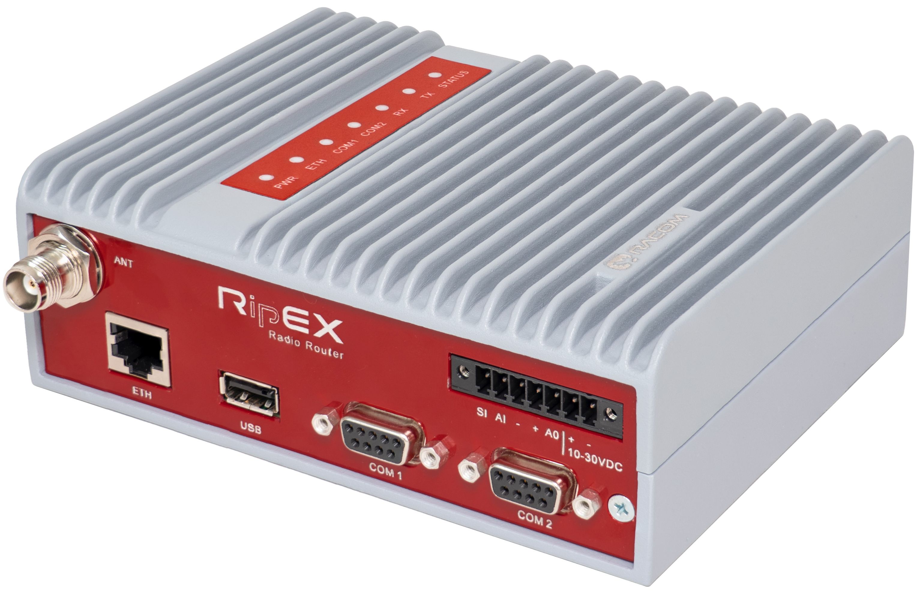
Table of Contents
- Important Notice
- Quick guide
- 1. RipEX – Radio router
- 2. RipEX in detail
- 2.1. Applications
- 2.2. Bridge mode
- 2.3. Router mode
- 2.3.1. Router – Flexible, Detail description
- 2.3.2. Router – Flexible, Functionality example
- 2.3.3. Router – Flexible, Configuration examples
- 2.3.4. Router – Flexible, Addressing hints
- 2.3.5. Router – Base driven, Detail description
- 2.3.6. Router – Base driven, Functionality example
- 2.3.7. Router – Base driven, Configuration example
- 2.4. Serial SCADA protocols
- 2.5. Combination of IP and serial communication
- 2.6. Diagnostics & network management
- 2.7. Firmware update and upgrade
- 2.8. Software feature keys
- 3. Network planning
- 4. Bench test
- 5. Product
- 6. Installation
- 7. Advanced Configuration
- 8. CLI Configuration
- 9. Troubleshooting
- 10. Safety, regulations, warranty
- 10.1. Frequency
- 10.2. Safety distance
- 10.3. High temperature
- 10.4. RoHS, WEEE and WFD
- 10.5. Hazardous locations
- 10.6. Conditions of Liability for Defects and Instructions for Safe Operation of Equipment
- 10.7. Important Notifications
- 10.8. EU Declaration of Conformity RED
- 10.9. Simplified EU declaration of conformity
- 10.10. ATEX Certificate
- 10.11. IP51 Certificate
- 10.12. Compliance Federal Communications Commission
- 10.13. Country of Origin
- 10.14. Warranty
- 10.15. RipEX maintenance
- A. OID mappings
- B. Abbreviations
- Revision History