Step-by-step checklist
Mount RipEX into cabinet (Section 6.1.1, “DIN rail mounting”).
Install antenna (Section 6.2, “Antenna mounting”).
Install feed line (Section 6.3, “Antenna feed line”).
Ensure proper grounding (Section 6.4, “Grounding”).
Run cables and plug-in all connectors except from the SCADA equipment (Section 5.2, “Connectors”)
Apply power supply to RipEX
Connect configuration PC (Section 4.3, “Connecting RipEX to a programming PC”).
Configure RipEX (Chapter 7, Advanced Configuration ).
Test radio link quality (Section 4.5, “Functional test”).
Check routing by the ping tool (Section 7.6.3, “Ping”) to verify accessibility of all IP addresses with which the unit will communicate.
Connect the SCADA equipment
Test your application.
| Note – hazardous locations | |
| Installation in hazardous locations has to be done according to standard | |
| EN 60079-25 Explosive atmospheres Intrinsically safe electrical systems. |
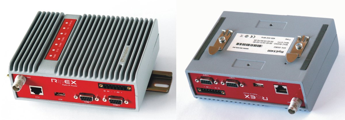
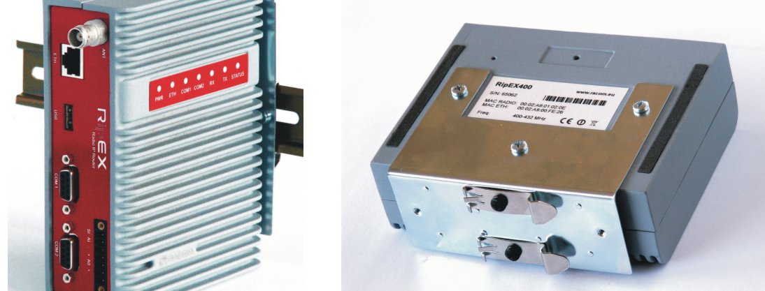
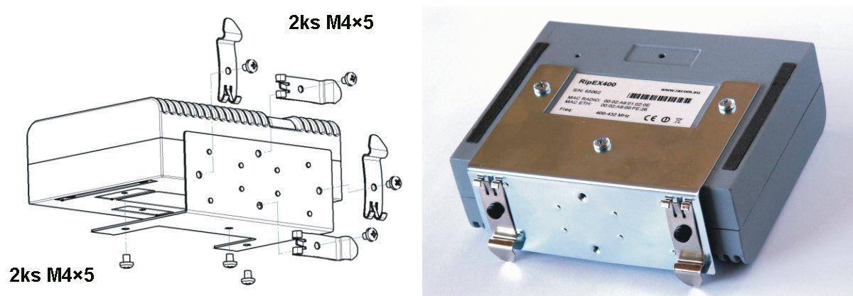
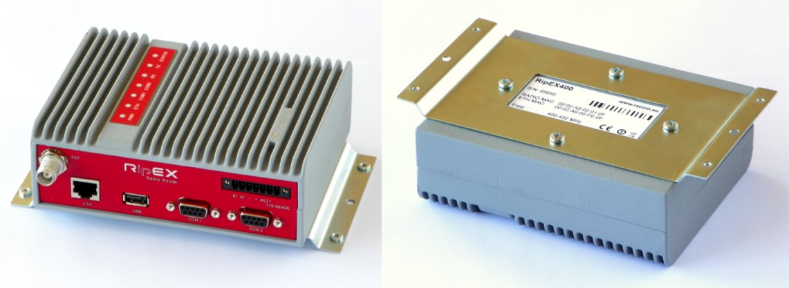
The radio modem RipEX is directly mounted using clips to the DIN rail. The mounting can be done lengthwise (recommended) or widthwise; in both cases with the RipEX lying flat. The choice is made by mounting the clips, one M4 screw per clip. RipEX is delivered with two clips, two screws and four threaded holes. Only use the M4×5 mm screws that are supplied. Use of improper screws may result in damage to the RipEX mainboard!

When tightening the screw on the clip, leave a 0,5 mm gap between the clip and the washer.
For vertical mounting to DIN rail, L-bracket (optional accessory) is used. Only use the M4×5 mm screws that are supplied. Use of improper screws may result in damage to the RipEX mainboard!
For more information see Section 5.6, “Accessories” – L-bracket.
For flat mounting directly to the support you must use the Flat bracket (an optional accessory). Only use the M4×5 mm screws that are supplied. Use of improper screws may result in damage to the RipEX mainboard!
For more information see Section 5.6, “Accessories” – Flat-bracket.
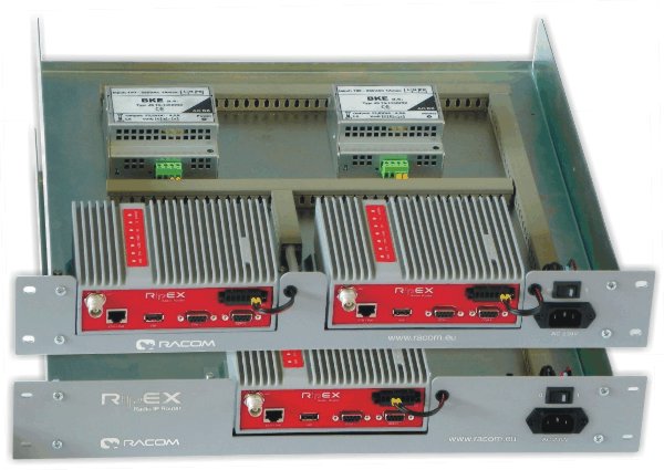
For installation into the 19″ rack you can use the 19″ rack shelf – single or 19″ rack shelf- double for one or two RipEX units. 19″ rack shelf is an optional accessory delivered with/without a power supply.
To meet IP51 protection requirements, two conditions must be met:
RipEX unit must host the “IP51 protection” option which is indicated by the letter “P” in the order code (e.g. RipEX-400SP).
RipEX unit must be physically installed with the connectors facing downward.
The type of antenna best suited for the individual sites of your network depends on the layout of the network and your requirements for signal level at each site. Proper network planning, including field signal measurements, should decide antenna types in the whole network. The plan will also determine what type of mast or pole should be used, where it should be located and where the antenna should be directed to.
The antenna pole or mast should be chosen with respect to antenna dimensions and weight, to ensure adequate stability. Follow the antenna manufacturer’s instructions during installation.
The antenna should never be installed close to potential sources of interference, especially electronic devices like computers or switching power supplies. A typical example of totally wrong placement is mount a whip antenna directly on top of the box containing all the industrial equipment which is supposed to communicate via RipEX, including all power supplies.
Additional safety recommendations
Only qualified personnel with authorisation to work at heights are entitled to install antennas on masts, roofs and walls of buildings. Do not install the antenna in the vicinity of electrical lines. The antenna and brackets should not come into contact with electrical wiring at any time.
The antenna and cables are electrical conductors. During installation electrostatic charges may build up which may lead to injury. During installation or repair work all open metal parts must be temporarily grounded.
The antenna and antenna feed line must be grounded at all times.
Do not mount the antenna in windy or rainy conditions or during a storm, or if the area is covered with snow or ice. Do not touch the antenna, antenna brackets or conductors during a storm.
The antenna feed line should be chosen so that its attenuation does not exceed 3 to 6 dB as a rule of thumb, see Chapter 3, Network planning. Use 50 Ω impedance cables only.
The shorter the feed line, the better. If RipEX is installed close to antenna, the data cable can be replaced by an Ethernet cable for other protocols utilising the serial port, see Advanced Configuration, Terminal server. This arrangement is recommended especially when the feed line would be very long otherwise (more than 15 meters) or the link is expected to operate with low fading margin.
Always follow the installation recommendations provided by the cable manufacturer (bend radius, etc.). Use suitable connectors and install them diligently. Poorly attached connectors increase interference and can cause link instability.
To minimise the odds of the transceiver and the connected equipment receiving any damage, a safety ground (NEC Class 2 compliant) should be used, which bonds the antenna system, transceiver, power supply, and connected data equipment to a single-point ground, keeping the ground leads short.
The RipEX radio modem is generally considered adequately grounded if the supplied flat mounting brackets are used to mount the radio modem to a properly grounded metal surface. If the radio modem is not mounted to a grounded surface, you should attach a safety ground wire to one of the mounting brackets or a screw on the radio modem’s casing.
A lightning protector should be used where the antenna cable enters the building. Connect the protector to the building grounding, if possible. All grounds and cabling must comply with the applicable codes and regulations.
RipEX uses standard connectors. Use only standard counterparts to these connectors.
You will find the connectors’ pin-outs in chapter Section 5.2, “Connectors”.
We do not recommend switching on the RipEX’s power supply before connecting the antenna and other devices. Connecting the RTU and other devices to RipEX while powered increases the likelihood of damage due to the discharge of difference in electric potentials.
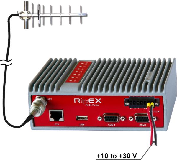
RipEX may be powered from any well-filtered 10 to 30 VDC power source. The supply must be capable of providing the required input for the projected RF output. The power supply must be sufficiently stable so that voltage doesn’t drop when switching from receiving to transmission, which takes less than 1.5 ms. To avoid radio channel interference, the power supply must meet all relevant EMC standards. Never install a power supply close to the antenna. Maximal supply cable length is 3 m.
| Warning – hazardous locations | |
| The unit must be powered with an intrinsic save power source for use in hazardous locations. |