Racom routers are built into a robust metal case and are suitable for applications which place them in various environments from air-conditioned offices to heavy industry factories. To a certain extent the method of installation needs to be adapted to this. All information in this chapter describes the standard method of installation for normal industrial applications, which has been derived from valid regulations for such equipment and also from the long-term experience of our engineers. In the case of larger-scale networks and more complicated applications we recommend that users order a project assessment from Racom, or a partner company, which should consist of careful measurements of the strength and quality of a signal and an assessment of the conditions for the propagation of radio waves.
A power supply meeting the specified parameters (see the table of technical parameters) needs to be used for supplying radio routers. We recommend using an MS2000 power supply or other power supply of MORSE system , which has been developed specially for these purposes, and where necessary is capable of switching to a back-up battery, as well as monitoring its state of charge, and also charging.
The Data Terminal Equipment, a programmable controller, a PC or any other device communicating over the radio network, has to be connected to the router by a data cable to the serial or the Ethernet interface according to the respective standard. These interfaces are described in detail in the chapter Connectors.
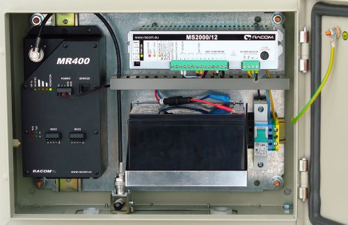
Radio routers can be mounted either to a mounting plate using screws or by mounting on a DIN rail. See the table of technical parameters for the dimensions and spacing separation of mounted parts. Generally for industrial applications the radio routers are mounted together with the overvoltage protection, power supply, and back-up battery into a switchboard with IP54 protection.