The cable for connecting the antenna is fitted with an FME type connector. Use a connector of the corresponding type and impedance as its mate.
| Important | |
|---|---|
CAUTION. The router cannot be connected to the power supply without the antenna connected (or corresponding artificial load). Otherwise this could lead to damage to the radio part of the router. |
The router can be equipped with serial ports RS232 or RS422/485, the ports can be optical isolated. According to the configuration it is possible to use a terminal block or DSUB 9 (Canon) connectors for connecting data cables via the serial interface. See Chapter Dimensional Diagram and Labeling. Data rate on the serial interface can be from 200 bps to 230,400 bps.
a) Table of data connector RS232 connections
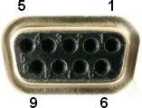
Tab. 3.1: Table of data connector RS232 connections
| RS232 signal | Screw terminals | DSUB9F pin |
|---|---|---|
| CTS | 1 | 8 |
| RTS | 2 | 7 |
| RxD | 3 | 2 |
| TxD | 4 | 3 |
| GND | 5 | 5 |
| DTR | 4 | |
| DSR | 6 | |
| CD | 1 | |
| RI | 9 |
b) Table of data connector RS422 connections
Tab. 3.2: Table of data connector RS422 connections
| RS422 signal | Screw terminals | DSUB9F pin |
|---|---|---|
| TxD- | 1 | 7 |
| TxD+ | 2 | 3 |
| RxD- | 3 | 8 |
| RxD+ | 4 | 2 |
| GND | 5 | 5 |
c) Connection diagram of data cable RS485
When you are connecting RS485, your “A” has to be connected to TxD+ and RxD+ simultaneously and “B” to TxD- and RxD- simultaneosly.
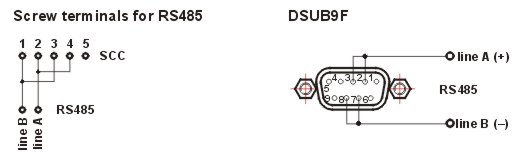
Note – For data connector RS485 connection see Table of data connector RS422 connections.
Important – For making data cables for connecting the user´s terminal equipment to the serial port we recommend using a shielded cable, particularly in an industrial environment, and connecting the shielding to GND (pin No. 5). When using a multi-core cable all free conductors should be connected to pin No. 5. In the case of a galvanically separate port for RS485 (RS422) only ground one side of the data cable. We recommend using only the necessary minimum length for data cables.
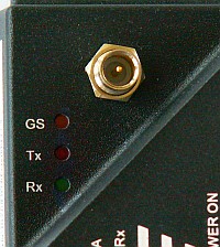
For RS232 RxD is the output from the router (approx. -6V when inactive) and TxD is the input to the router (according to the RS 232 standard). Hardware versions of the interface can be distinguished according to the colours of LED diodes next to the connector.
The SCC ports of the router are DCE type devices. Based on standards the receiver terminal RxD of the connected DTE device is connected to the transmitting terminal of the router’s SCC port which is also labelled RxD. Similarly the red LED indicating transmission from SCC is labelled RxD.
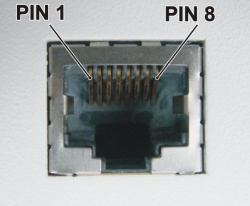
Connector RJ-45 for Ethernet 10BaseT and 100BaseT corresponds to the EIA TIA T568B standard.
Informative LED diodes indicate:
Tx – yellow – output or input active (*Tx – red – output from ETH channel)
Rx – yellow – output or input active (*Rx – green – input to ETH channel
![[Note]](/images/radost/images/icons/note.png)
Note Green LED Tx and yellow LED Rx flash simultaneuosly. The informations marked (*) are valid for hw version produced until 07/2008.
100 – yellow – if lit the 100Base-TX net is indicated otherwise is 10Base-T
LINK – green – indicates correctly connected link
F.D. – green – indicates full duplex operation
The direct cable serves for connecting to the Ethernet network via the hub (repeater) or switch-hub (router).
A crossed cable serves for connecting only two devices – MR400-MC100, MR400-PC, etc.
The ETH module consumption is 30 mA (60 mA until 07/2008).
The following table contains connector connections and colours of conductors. For the crossed cable the order of conductors on one side is the same as for the direct cable.
The module of analog and digital inputs and outputs (ADIO) is designed for :
creating 20 mA current loops
switching loads supplied with DC and AC current
scanning digital signals
Each functional group of terminals is galvanically separated from the rest of the device as shown on the internal layout diagram for the ADIO module on the image below:
Individual terminals of terminal blocks are labelled:
| Connector A OUT | – analog outputs |
| Connector A IN | – analog inputs |
| Connector D OUT | – digital outputs |
| Connector D IN | – digital inputs |
| Terminal UP | this clamps pair is not used |
Tab. 3.5: Table of digital and analog input and output parameters
2 × optically separated digital output | – bipolar SSR switch design – voltage for supplying load max. 30 V DC, 24 V AC – switched current typically 300 mAresistance in on state max. 1 Ω – protection against current overload in on state – protection against overvoltage in off state | passive |
2 × optically separated digital input | – passive optical element design – input voltage 0–2,3 V will be evaluated as log. 0 – input voltage 2–30 V will be evaluated as log. 1 – max. value of input voltage 30 V | passive |
2 × optically separated analog output | – current source 4–20 mA – load resistance max. 250 Ω – settings accuracy better than 0.1 % | active |
2 × optically separated analog input | – sensitivity 0–20 mA (or after sw configuration
4–20 mA) – accuracy of measured values better than 0.1 % – input resistance 60 Ω – no protection against current overload – max. value of input current 50 mA | passive |
Analog inputs 0 and 1 have – (minus) terminals connected and galvan. separated from router GND.
Analog outputs 0 and 1 have – (minus) terminals connected and galvan. separated from router GND.
Terminals of this connector are labelled in the standard manner. Only DC voltage in the range from 10.8 to 15.6 V can be connected. Connecting higher voltage may damage the router.
Terminal PI (power indicator) – if the router is fed from the MS2000 power supply information about supply method from source clamp MAIN PWR OFF can be lead:
level TTL1 or unconnected clamp – network supply
level TTL0 or grounded clamp – battery supply
Maximal supply cable length is 3 m.
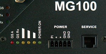
Information LED diodes next to the supply connector:
Tab. 3.6: Modes of LED diodes Power
| LED name | LED mode | Operating state | |
|---|---|---|---|
| GS A | red, shining | Module attached to GSM network and PPP connection is established. | |
| GS Rx | green, flashes | Receiving data (GPRS/UMTS). | |
| low+middle +high | 3 yellow LEDs | rss, signal better then -79 dBm | These LEDs are refreshed after expiring of Info timeout of the router (SXe r 1g). If this timeout is set to zero then router displays the rss at the moment of init of PPP protocol (typically at the router restart). |
| low+middle | 2 yellow LEDs | rss, signal better then -89 dBm | |
| low level | 1 yellow LED | rss, signal better then -107 dBm | |
| POWER ON | green, shining | POWER ON — router is correctly supplied | |
Meaning of LED diodes by the antenna connector
LED diodes by the antenna connector signal the status and operation of the GPRS/UMTS module which is located below the partition in the radio part of the router.
| GS | GPRS/UMTS status – diode flashes in different modes, the meaning is given in the table bellow. This is conditional upon setting up the appropriate parameters of PPP protocol in the SPe menu. |
| TX | communication between the GSM module and the MG100 router – transmission of data from the modem to the module |
| RX | communication between the GSM module and the MG100 router – receipt of data to the modem from the module |
Tab. 3.7: Modes of LED diode GS for MG100M, MG100M2and MG100M3
| GS LED mode | Operating state |
|---|---|
| lightless (OFF) | Module has no supply, or is in SLEEP mode. |
| flashes quickly (0,5 s ON/0,5 s OFF) | Location of network underway, or module is not attached to the network, or SIM card not inserted, or PIN code not entered. |
| flashes slowly (0,3 s ON/2,7 s OFF) | GSM module attached to the
network (cellular net connected). |
| steady light (ON) | Ongoing communication. |
Tab. 3.8: Modes of LED diodes GS for MG100M4
| GS LED mode | Operating state |
|---|---|
| lightless (OFF) | Module has no supply. |
| steady light (ON) | Ongoing network search and registration in it. |
| flashes slowly (0,8 s ON/0,8 s OFF) | The module is registered in GSM network. |
| flashes quickly (0,2 s ON/0,2 s OFF) | Ongoing communication. |
Tab. 3.9: Modes of LED diodes GS for MG100M0
| LED mode | Operating state |
|---|---|
 | Module has no supply, or alarm mode, or NONCYCLIC SLEEP mode, or CYCLIC SLEEP mode waiting for awakening. |
 | SIM card not inserted, or PIN code not entered, or location of network underway, or user verification underway, or logging on to network underway. |
 | IDLE mode: Device registered in GSM network, data transmission not taking place. |
 | PDP context activated, connection made to GPRS network – normal status for MORSE/GPRS system. |
 | Packet transmission of data underway. |
 | Connection to remote module – only in the case of CSD, doesn’t occur in the case of GPRS. |
The service connector RJ-12 serves for short-term connections of the service cable during local adjustment of MORSE router parameters. Upon attaching the connector (connecting to the RS232 link (RxD,TxD, GND)) the router automatically switches to service mode and the module slot 1 disconnects. Slots numbering see section Section 3.9, “View of MG100 router”.
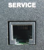
Tab. 3.10: Table of service connector connections
| 1 | AF_OUT | output of modulation from RF part of router |
| 2 | SER_RxD | RS232 RxD output from router |
| 3 | SER_TxD | RS232 TxD input to router |
| 4 | MOD_BSB | input modulation to radio part of router |
| 5 | GND | ground |
| 6 | PTT | keying of TX carrier waves for service purposes |
| Important | |
|---|---|
ATTENTION! The service mode is not suitable for normal operation |
There is an opening at the bottom edge of the right side of the router through which the SIM card holder is inserted into the plug-in reader.
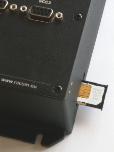 | 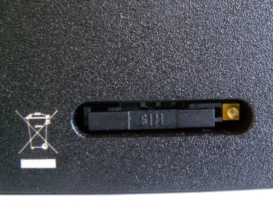 |
The SIM card holder is released by pressing the yellow ejector button inside the opening next to the SIM card holder using a suitable sharp tip, e.g. a ballpoint pen.