The following chapters will guide you step by step through preparation, installation and activation of the RAy link:
Pre-installation check out
Pre-installation Checklist
Familiarise yourself with the controls and prepare your configuration ahead of the installation of the link on the mast tube.
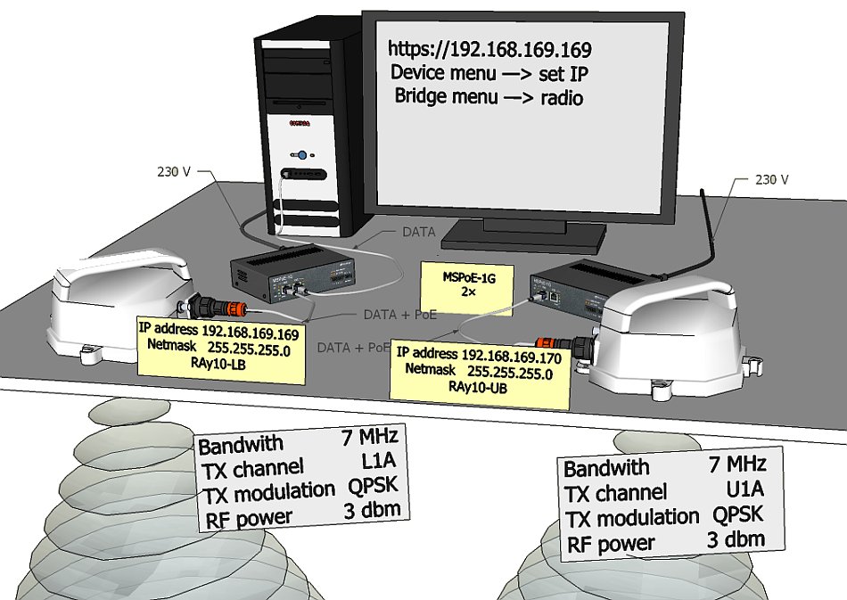
Both units (without antennas) can lie on a desk with flanges running parallel and facing up at an angle, on a non-metal desk they can also face downward. Turn unit holders so that they are roughly parallel to each other. Use an ethernet cable to connect each of the units to a PoE source and connect a PC to one of them for configuration.
Take the following steps to establish a connection between the PC and RAy and perform a basic setup.
RAy link is supplied with a default configuration of access parameters or a customised configuration tailored to customer’s needs.
In this default state the following access parameters are set:
Unit L has the service IP address 192.168.169.169 and mask
255.255.255.0,
Unit U has the service IP address
192.168.169.170 and mask 255.255.255.0,
access is allowed
over HTTPS or ssh with a key,
the username is
admin and the password is also
admin.
On your PC setup an IP address that is within the mask, i.e. 192.168.169.180.
Then open the https configuration interface, e.g.
https://192.168.169.169.
Other access options are described in the chapter Device – Service Access of this manual.
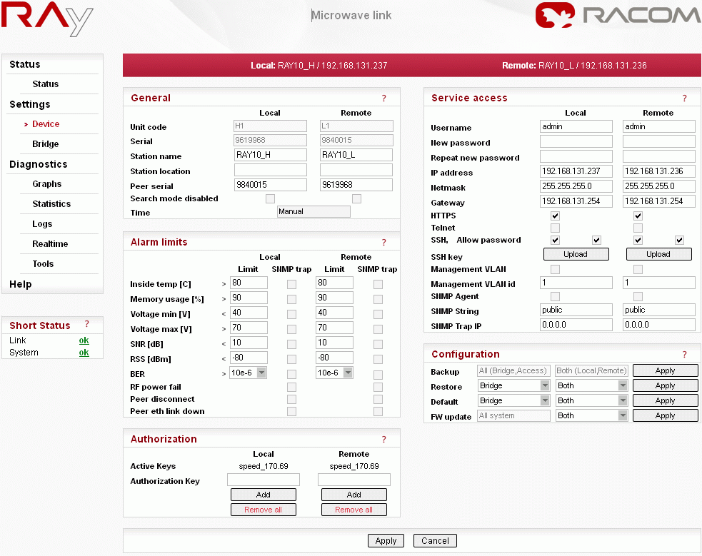
When connection has been established, use the Device menu to customise access parameters. Default IP addresses should be replaced with well-chosen operating addresses. Leaving default addresses in place can lead to later network problems.
The menu contains parameters for the entire link, both for the local and remote units. If a connection has been established, both sets of parameters have been set. While working with an isolated unit, only local parameters are functional for the currently connected unit.
The configuration described above is the default Access open setup, see Settings/Device/Configuration/Default.
| Note | |
|---|---|
If there is any problem with https certificate after completing the firmware upgrade, please see the Appendix F, Https certificate for further steps. |
Station name – station can be indicated by name, e.g. according to the place of installation
Peer serial – serial number of peer station, recorded during production
Username – enter your name and enter your new password concurrently
New password – choose your access password and write it in
Repeat new password – write in the password again
IP address – write in the valid IP address for the access to the station. The default IP address must be replaced by a valid address. Keeping the default address will most probably lead to future problems within the network.
Netmask – write in the mask
Gateway – if necessary, write in the gateway or leave the item empty
Allow the access protocols you will need. For safety reasons, do not allow more than necessary:
HTTPS, Telnet – access permission
SSH, Allow passwd – the first mark allows access with a key, both marks allow access with a password, without a key
Save the menu content by clicking on the button Apply.
Default parameters for the line are configured for channels L1a and U1a, bandwidth 7 MHz, modulation QPSK, coding High, output 3 dBm and are ready to establish contact. If it is possible to work with these channels in the considered site, you can install and run the link. Then set the real operation configuration on the running link.
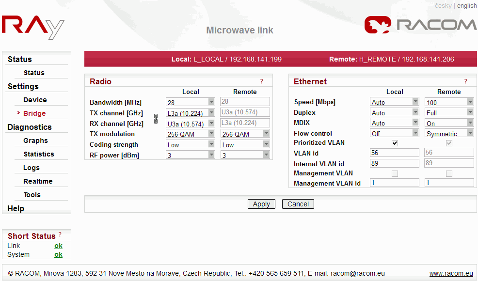
If changes need to be implemented, perform them in the menu Settings a save them by the command Apply. Again, you are working with both stations at once if they are in contact, otherwise configure the stations separately. Pay attention to correct configuration of duplex pairs of TX and RX channels while configuring separately. For example, if one station (RAy10-LB) has the TX channel L1a, then the second station (RAy10-UB) must have the RX channel L1a, too.
Authorization keys
To fully utilize the transmission rate and transmit power is necessary to use the software Authorization keys. Without keys the link works with the lowest modulation QPSK / 8,45 Mbps only and with power at most 3 dBm.
Under Settings/Device/Authorization input your key (29 letters, digits and symbols long) and click Add. Using the key opens up advanced options for Bandwidth, Modulation and Coding strength or RF power for the respective unit. To find out more about keys, refer to the Device – Authorization chapter.
Example of configuration in the menu Settings Bridge:
Verify the status of the radio link:
Short Status displays Link ok.
If instead of System ok the message displayed is System alarm, this doesn’t necessarily mean there is a problem. The message indicates that the limit of one of the parameters has been exceeded. Essential is the Link ok message.The menu contains values for both local and remote units. N/A next to Remote indicates that the data from the remote unit has not been transferred. If Link is ok, simply click Refresh at the bottom of the screen and Remote data will be updated.
Status/Radio shows the RSS and SNR links and the selected modulation and Net bit rate for ACM.
Diagnostics/Realtime shows the current RSS, SNR and BER.
Menu Diagnostics/Ping enables ping-testing the other unit.
Test modulation options:
ACM modulation – under Settings Bridge/Radio setup TX modulation ACM. Refresh Status/Radio to monitor the changes in modulation based on the quality of signal SNR. The status and quality of modulation are well shown by setting Diagnostics Tools/RX constellation diagram, Read Continuously to Yes.
To set a fixed modulation go to Settings Bridge/Radio and set the TX modulation to a value from the range of QPSK through 256-QAM based on the results of the previous test. If you choose modulation higher than allowed by SNR, the connection will be lost. Short Status Link will lose its ok value. Both units will need to be moved closer to resume the link. If this is not possible, use ethernet to access each unit individually and set the basic modulation QPSK. You can monitor the quality of the received signal under Diagnostics Tools/RX constellation diagram.
Verify the functionality of the entire link:
If possible, connect user devices to both RAy units over PoE and test mutual communication.
Another way of testing this is to connect a PC to the other unit and send a ping from one PC to the other.
The minimum variant of this test is to use ethernet cable connection from the PC connected to the local RAy to the PC connected to the remote RAy and test communication between both units over ethernet. This will verify ethernet functionality.
Prepare installation configuration:
Bandwidth 7 MHz
TX channel within the supposed range, e.g. use 7 MHz channel L6a inside the 28 MHz L2a range, see Frequencies table.
RX channel will setup automatically when channel lock activates.
TX modulation QPSK
Coding strength High
RF power +3 dBm
To save click Apply.
Record the access parameters from the Service access menu, especially the IP addresses.
Restart by interrupting power supply to verify that the parameters are stored correctly and the link works.
After this preparation phase you can continue to install your devices in working environment.


