Both serial and Ethernet SCADA masters are supported.
![RipEX-HS dimensions [mm]](/images/radost/dummy/dummy/../../images/hw/RipEX/ripex-hs_rozm.jpg)
Since there are two independent power supplies, one for each RipEX unit, it is recommended to connect each power supply to a separate power phase with individual circuit breakers. When one phase would be off, RipEX-HS will still be On.
There are individual power connectors for each power supply. See Section 3.3.2, “A and B connectors”.
There are also two independent power supplies with 36 to 60 V DC input voltage, one for each RipEX unit; input conductors are isolated from the rest of the RipEX-HS and thus allows positive or negative grounding. The electric strength is 4 kV AC/1 min.
| Note | |
|---|---|
When positive grounding is used, neither device connected via RS232, USB, ETH can have negative grounding ! |
There are individual power connectors for each power supply. See Section 3.3.2, “A and B connectors”.
There is not any internal power supply in this option, powering is the same as for standard RipEX.
The supply must be capable of providing the required input for the projected RF output. The power supply must be sufficiently stable so that voltage does not drop when switching from receive to transmit, which takes less than 1.5 ms. To avoid radio channel interference, power supply must meet all relevant EMC standards. Never install a power supply close to the antenna. Maximal supply cable length is 3 m, and recommended wire cross section 1.0 mm2.
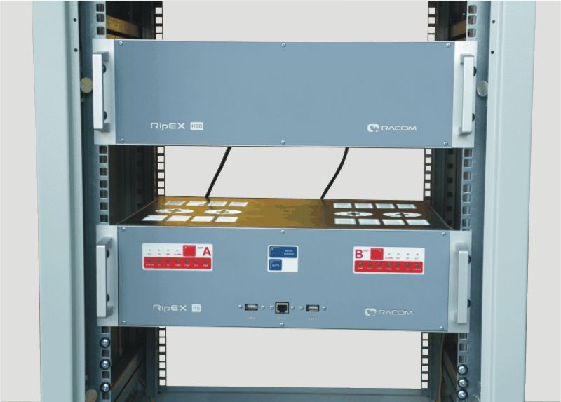
When back-up battery is required, RipEX-HSB battery pack can be connected. RipEX-HSB is individual 19″ rack 3U box assembled with separate batteries for RipEX “A” and “B”. There is space for 4x 12 V / 7.2 Ah batteries inside. Batteries are charged-up from RipEX-HS. RipEX-HSB provide approx. 10 hours of total RipEX-HS operation.
Generally not only RipEX-HSB, but any battery, even with higher capacity, can be used. PSC-100B power supply is used in RipEX-HS. Its battery charger output is 27,6 V/1,25 A. So battery charge time is equal to max. charge current.
| Note | |
|---|---|
Primary AC power has to be active first, otherwise the battery back-up will not be working. |
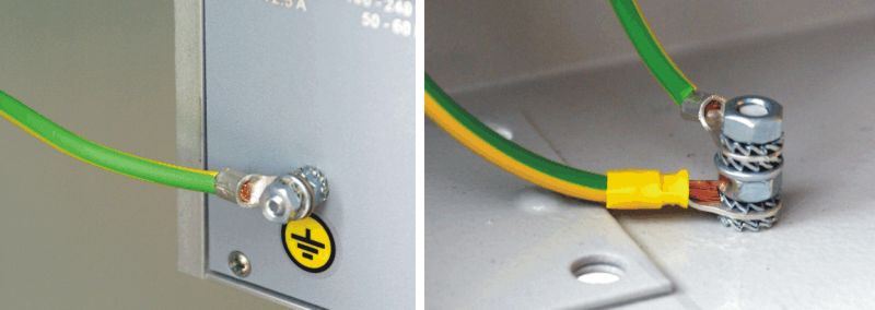
The grounding screw on the rear panel has to be properly connected to the grounding point of the rack. The minimal required copper conductor cross-section is 4 mm2.
For antenna installation refer to RipEX User manual – https://www.racom.eu/eng/products/m/ripex/instal.html#antenna-mount