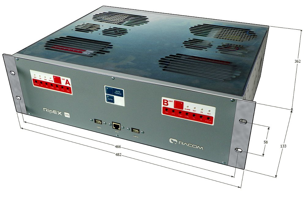
19″ rack 3U, 482 W × 401 D × 133 H mm, 18.98 W × 15.79 D × 5.24 H inch.
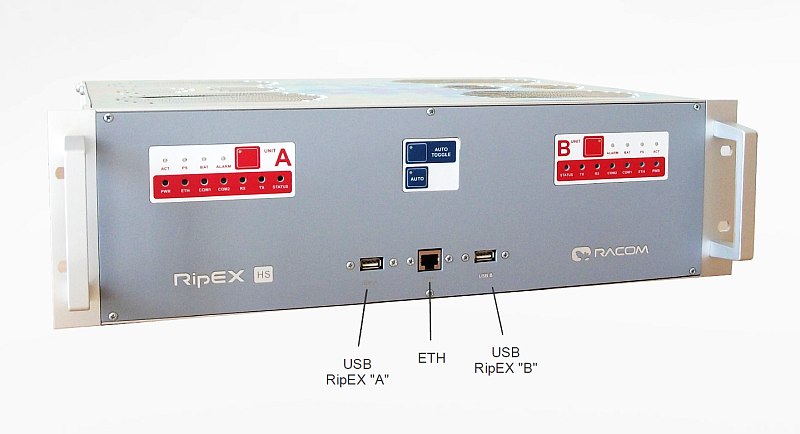
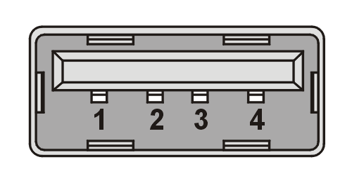
RipEX uses USB 1.1, Host A interface. USB interface is wired as standard:
The USB interface is designed for connection to the external ETH/USB adapter, which is an optional accessory to RipEX, for more see Section 5.3, “Connecting RipEX to a programming PC” – user manual for RipEX. The adapter is used for service access to RipEX’s web configuration interface.
Both USB A and USB B are internally hard-wired to the corresponding RipEX unit.
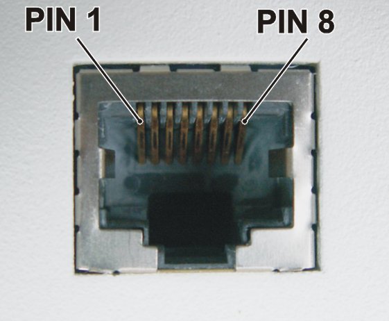
Standard RJ45 connector 10/100 BaseT Auto MDI/MDIX – connected to the internal ETH switch.
Please note: only active RipEX unit can be accessed using the ETH interface
Tab. 3.2: Connections for the Ethernet to cable connector
| PIN | Signal | Direct cable | Crossed cable |
|---|---|---|---|
| 1 | TX+ | orange – white | green – white |
| 2 | TX− | orange | green |
| 3 | RX+ | green – white | orange – white |
| 4 | — | blue | blue |
| 5 | — | blue – white | blue – white |
| 6 | Rx− | green | orange |
| 7 | — | brown – white | brown – white |
| 8 | — | brown | brown |
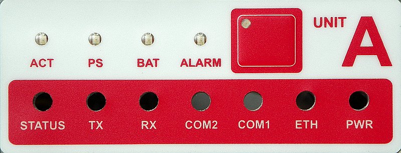
Tab. 3.3: LED panel description
| Symbol | Description | |
|---|---|---|
| 1 | ACT | green – RipEX A is active dark – RipEX A is not active |
| 2 | PS | green – input (primary) power supply A is OK (ON) dark – the power supply A is without power or is powered by battery |
| 3 | BAT | red – battery voltage is less then 22 V dark – battery disconnected or battery voltage is OK |
| 4 | ALARM | red – RipEX is in alarm status dark – no alarms |
The lower row of LEDs have the same meaning as the LEDs on RipEX LED panel.
| Note | |
|---|---|
PS and BAT LEDs are not used with RipEX-HS-EY (the main power supply 11 to 30 VDC). |
Tab. 3.4: Key to LEDs
| Color | Description | |
|---|---|---|
| STATUS | Green | RipEX OS (Linux) is running successfully |
| Dark | Reset button has been pressed | |
| Green flashes slowly | reset five-seconds after pressing the Reset button | |
| Green flashes quickly | default access 15-seconds after pressing the Reset button | |
| Red | Status alarm | |
| TX | Red | transmitting to radio channel |
| RX | Green | receiver is synchronised to a packet |
| Yellow | there is a signal stronger than −80 dBm on Radio channel | |
| COM2 | Green | receiving data |
| Yellow | transmitting data | |
| COM1 | Green | receiving data |
| Yellow | transmitting data | |
| ETH | Yellow ON | 100 Mb/s speed |
| Yellow OFF | 10 Mb/s speed | |
| Green ON | connected | |
| Green flashes | ethernet data | |
| PWR | Green | powered successfully |
| Blinks with a period of 1 sec | Save mode | |
| Flashes once per 3 sec | Sleep mode |
Active when green LED is on:
 | Auto toggle – the same as Auto mode, in addition after set time controller automatically switches-over to RipEX „B“, even if “A” doesn’t have any alarm and uses “B” for set period in order to confirm, that RipEX „B“ is fully ready-to-operate. |
 | Auto – primary active unit is RipEX „A“, and the controller automatically switches-over to RipEX „B“ when “A” fails. When both units fail, unit „A“ remains active. |
 | A – Unit A is active. It will never switch to the B unit. This mode is recommended only for the maintenance/testing use and not for normal service. |
 | B – Unit B is active. It will never switch to the A unit. This mode is recommended only for maintenance/testing use and not for normal service. |
For more see Section 2.3, “Operating modes”.
| Note | |
|---|---|
When testing the changeover, please wait at least 30 seconds between individual tests. |
2× ETH
Standard RJ45 connector 10/100 BaseT Auto MDI/MDIX – connected to the internal ETH switch.
Tab. 3.5: Connections for the Ethernet to cable connector
| PIN | Signal | Direct cable | Crossed cable |
|---|---|---|---|
| 1 | TX+ | orange – white | green – white |
| 2 | TX− | orange | green |
| 3 | RX+ | green – white | orange – white |
| 4 | — | blue | blue |
| 5 | — | blue – white | blue – white |
| 6 | Rx− | green | orange |
| 7 | — | brown – white | brown – white |
| 8 | — | brown | brown |
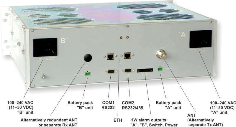
RipEX HS provides two serial interfaces COM1 and COM2 terminated by DSUB9F connectors.
COM1 is always RS232, COM2 can be configured as RS232 or RS485.
– both COMs
are internally switched to the active RipEX unit.
RipEX‘s RS232 is a hard-wired DCE (Data Communication Equipment) device. Equipment connected to the RipEX’s serial ports should be of DTE (Data Terminal Equipment) type and a straight-through cable should be used. If a DCE device is connected to the serial ports RipEX, a null modem adapter or cross cable has to be used.
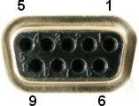
Tab. 3.6: COM1,2 pin description
| DSUB9F | COM1, 2 – RS232 | COM2 – RS485 | ||
|---|---|---|---|---|
| pin | signal | In/ Out | signal | In/ Out |
| 1 | CD | Out | — | |
| 2 | RxD | Out | line B | In/Out |
| 3 | TxD | In | line A | In/Out |
| 4 | DTR | In | — | |
| 5 | GND | GND | ||
| 6 | DSR | Out | — | |
| 7 | RTS | In | — | |
| 8 | CTS | Out | — | |
| 9 | — | — | — | |
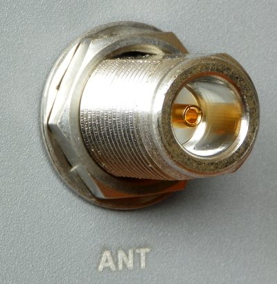
There are different models in terms of antenna connectors, see Section 3.5, “Model offerings”. N-female connector is always used. The coaxial surge protection is internally used for each antenna connector.
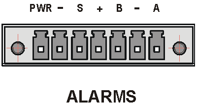
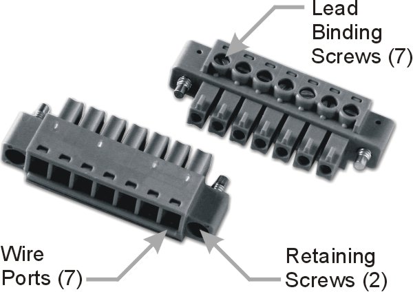
This rugged connector connects to Alarms provided by RipEX-HS. A Plug with screw terminals and retaining screws for Alarm connector is supplied with each RipEX_HS. The connector is a Tyco 7 pin terminal block plug, part No. 1776192-7, contact pitch 3.81 mm. It is designed for electric wires with a cross section of 0.5 to 1.5 mm2. Strip the wire leads to 6 mm (1/4 inch). Isolated cables should receive PKC 108 or less end sleeves before they are inserted in the clip. Insert the cables in the wire ports, tightening securely.
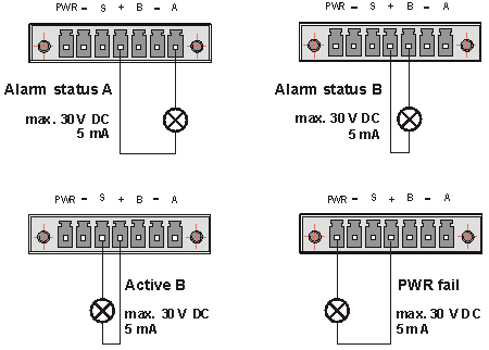
Tab. 3.7: Alarms description
| Symbol | Description |
|---|---|
| A | – alarm status of RipEX A – open collector – internally connected to GND when unit is not in alarm status |
| B | – alarm status of RipEX B – open collector – internally connected to GND when unit is not in alarm status |
| – | – connected to ground |
| + | – connected to +24 V power (max. 5 mA) |
| S | – open collector – internally connected to GND when unit A is
active – i.e. not switched to backup unit |
| PWR | – internal power alarm – open collector – internally connected to GND when controller power source is OK |
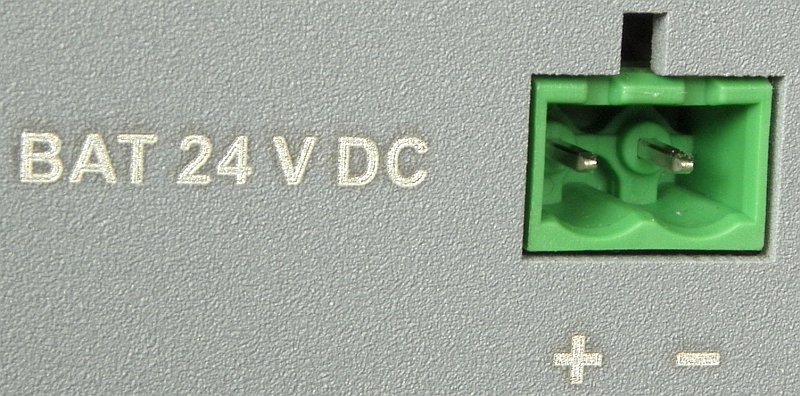
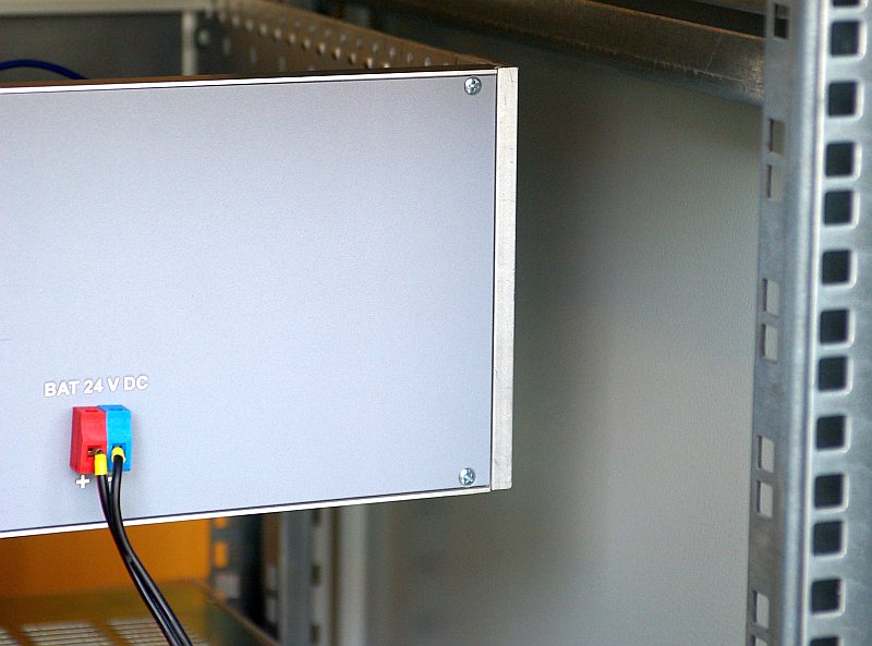
This rugged connector connects batteries in RipEX-HSB. A Plug with screw terminals and retaining screws for Battery connector is supplied with each RipEX-HS. The connector is a Phoenix contact 2 pin terminal block plug, part No. 1757019, contact pitch 5.08 mm. It is designed for electric wires with a cross section of 0.2 to 2.5 mm2. Strip the wire leads to 7 mm. Isolated cables should receive PKC 2507 or less end sleeves before they are inserted in the clip. Insert the cables in the wire ports, tightening securely.
+ to be connected with + pole of 24 V
battery
– to be connected with – pole of 24
V battery
| Important | |
|---|---|
internally without a fuse |
Radio parameters | |||
| The same as RipEX units used | |||
Electrical | |||
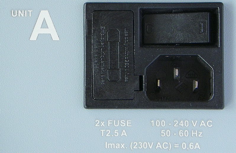
| Primary power | HW models: | 100–240 VAC, 50–60 Hz | |
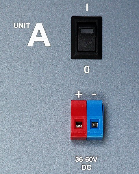
| 36–60 VDC, positive grounding possible | |||
| 11–30 VDC | |||
| Individual power supply for each RipEX unit | |||
Interfaces | |||
| Ethernet | 3× switched 10/100 Base-T Auto MDI/MDIX | RJ45 | |
| COM 1 | RS232 | DB9F | |
| 300–115 200 bps | |||
| COM 2 | RS232/RS485 SW configurable | DB9F | |
| 300–115 200 bps | |||
| USB | 2× USB 1.1 for each RipEX unit | Host A | |
| Antenna | 50 Ω | N-female(s) | |
| HW models (according to Antenna) | |||
| 1× N-female | – Rx/Tx, switched | ||
| 2× N-female | – Rx/Tx, separate for each RipEX unit | ||
| 2× N-female | – separate Rx and Tx, switched | ||
| 4× N-female | – separate Rx and Tx, separate for each RipEX unit | ||
| 2× N-female | – Migration, Rx/Tx output, Legacy base input | ||
| All antenna connectors are internally equipped with coaxial surge protection. | |||
Environmental | |||
| IP Code (Ingress Protection) | IP20; (* IP40 optionally) | ||
| MTBF (Mean Time Betw. Failure) | > 500.000 hours (> 50 years) | ||
| Operating temperature | −10 to +60 °C (14 to +140 °F); (* –40 to +70 °C optionally) | ||
| Humidity | 5 to 95 % non-condensing | ||
| Storage | −40 to +85 °C (−40 to +185 °F) | 5 to 95 % non-condensing | ||
Mechanical | |||
| Dimensions | 19″ rack 3U | 482 W × 401 D × 133 H mm (18,98 × 15.79 × 5,24 in) | |
| Weight | 7.1 kg (15.7 lbs), RipEX unit exl. | ||
| 9.1 kg (20.1 lbs), RipEX unit incl. | |||
Diagnostic and
Management | |||
| Standard for individual RipEX units used | |||
| LED panels | for each RipEX unit: standard RipEX LED panel (7×
tri-color LEDs: Power, ETH, COM1, COM2, Rx, Rx, Status) + 4× two-color LEDs: Active, Power supply, Battery, Alarm | ||
| HW Alarm outputs | RipEX A, RipEX B, Switch, Power | ||
Approvals | |||
| CE. FCC | |||
RipEX-HS has been designed to have minimum possible number of hardware variants. Different HW models are determined by power supplies, antenna connections and serial ports.
Trade name: | RipEX-HS |
Type: | RipEX-HS |
Code | (according to power supply, antenna connectors and serial ports):
|
RipEX-HS-xyz
x – power:
A – 100–240 VAC 50–60 Hz
D – 36–60 VDC, positive grounding possible
E – 11–30 VDC – for output power 10 W it is recommended to use input power above 11.5 VDC
C – 100–240 VAC 50–60 Hz for A unit, 36–60 VDC for B unit
y – antenna connectors:
O – 1× N-female – switched for A and B
R – 2× N-female – separate antennas for A and B units (no switching, redundant antennas)
S – 2× N-female – separate antennas for Tx and Rx (switched for A and B units,
RipEX-D model used)F – 4× N-female – separate antennas for Tx and Rx for A and B units (no switching,
redundant antennas, RipEX-D model used)M – 2× N-female – Migration, 1x Output switched for A and B, 1x Input for legacy base station
antenna output.
NOTE: Automatic Antenna Switch (on separate order) is mounted inside of RipEX-HS.
z – serial ports:
2 – two serial ports (COM1, COM2) – (standard configuration) – SW key RipEX-SW-COM2 is needed for both RipEX units to allow communication on COM2.
1 – one serial port (COM2) NOTE: COM1 serial port is used in this configuration for allowing remote access into both RipEX units
Standard RipEX_HS package contents:
RipEX-HS (without RipEX units) – 1 pc
Alarm plug connector (counterpart) – 1 pc
Rack cage nut + screw – 4 pcs
For AC power model in addition:
Battery plug connector (counterpart) – 2 pcs
Standard RipEX_HSB package contents:
RipEX-HSB (without batteries) – 1 pc
Battery plug connector (counterpart) – 2 pcs
Rack cage nut + screw – 4 pcs
| Note | |
|---|---|
RipEX units (on separate order) are always assembled in RipEX-HS when delivered from factory, because there would be many uncoupled cables inside, which is not good for transport. In case of failure of one RipEX unit, it is possible to exchange it in the field when necessary. |
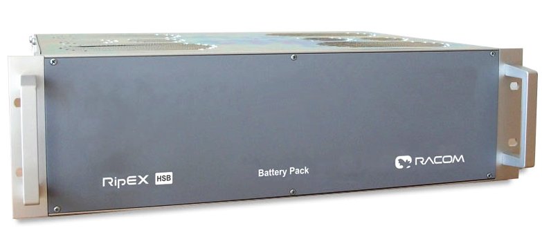
Back-up battery pack
Separate batteries for RipEX “A” and “B”, each unit is supplied independently
Batteries are charged-up from RipEX-HS (AC power version)
Individual 19″ rack 3U box
Space for 4x 12 V / 7.2 Ah, FASTON.250 (6.3 mm), e.g. Panasonic LC-R127R2P
Approx. 10 hours of total RipEX-HS operation, of both RipEX units together
Electrical | ||
| RipEX-HSB | battery pack | |
| Output 2× 24 V/7.2 Ah | ||
Environmental | ||
| Operating temperature | −15 to +50 °C (+5 to +122°F) | |
| Humidity | 25 to 85 % non-condensing | |
| Storage | −15 to +40 °C (+5 to +104 °F) max. 30 °C recommended, 25 to 85 % non-condensing | |
Mechanical | ||
| Dimensions | 19″ rack 3U | 482 W × 345 D × 133 H mm (18,98 × 13.58 × 5,24 in) |
| Weight | 3.5 kg (7.7 lbs), batteries exl. | |
| 13.1 kg (28.9 lbs), batteries incl. | ||
For more information about the operation of Lead Acid batteries, see http://www.panasonic-industrial.com/pf_vrla
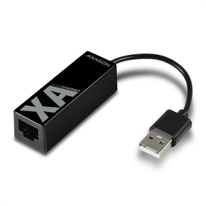
For service access to the RipEX web interface via USB connector
Built-in DHCP server
To access the RipEX always use the fixed IP 10.9.8.7
For more refer to RipEX User Manual, Accessories.
ETH/USB adapter for service access to the web interface via USB connector. Includes a built-in DHCP server which provides up to 5 leases. To access the RipEX always use the fixed IP 10.9.8.7. For details on use see RipEX manual, Bench test.
OTH-XA-ETH/USB requires FW 1.7.1.0 or higher. The previous model OTH-X5-ETH/USB is supported in all FW versions.
![RipEX-HSB dimensions [mm]](/images/radost/dummy/dummy/../../images/hw/RipEX/vykresHSB.gif)
