https//www.racom.eu/eng/products/m/ripex-hs/index.html
Table of Contents
- Important Notice
- Getting started
- 1. RipEX Hot Standby
- 2. RipEX-HS in detail
- 3. Product
- 4. Installation
- 5. Configuration
- 6. Troubleshooting
- 7. Safety, regulations, warranty
- 7.1. Frequency
- 7.2. Safety distance
- 7.3. Electric power shock hazard
- 7.4. High temperature
- 7.5. RoHS, WEEE and WFD
- 7.6. Conditions of Liability for Defects and Instructions for Safe Operation of Equipment
- 7.7. Important Notifications
- 7.8. Product Conformity
- 7.9. Compliance Federal Communications Commission
- 7.10. Country of Origin
- 7.11. Warranty
- A. Abbreviations
- Index
- Revision History
List of Figures
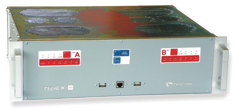
- 1. RipEX-HS
- 2.1. Block diagram
- 3.1. RipEX-HS dimensions
- 3.2. RipEX-HS front panel
- 3.3. USB connector
- 3.4. RJ-45F
- 3.5. A unit LED panel
- 3.6. RipEX-HS rear panel
- 3.7. RJ-45F
- 3.8. Serial connector
- 3.9. N connector
- 3.10. Alarm connector
- 3.11. Alarms cable plug
- 3.12. Alarms Outputs
- 3.13. Power supply connector AC model
- 3.14. Battery connector
- 3.15. Power supply connector DC model
- 3.16. RipEX-HSB
- 3.17. RipEX-HSB battery connector
- 3.18. RipEX-HSB dimensions [mm]
- 3.19. Adapter ETH/USB
- 4.1. HS connected as a SCADA centre redundant radio modem
- 4.2. RipEX-HS dimensions [mm]
- 4.3. RipEX-HS in 19″ Rack Cabinet
- 4.4. RipEX-HS montage using Assembly kit M6 – 4 pcs
- 4.5. RipEX-HS grounding in a cabinet
- 5.1. Menu Settings
- 5.2. Menu Hot-Standby
- 5.3. Menu Alarm management
- 7.1. EU Declaration of Conformity RoHS, WEEE
- 7.2. EU Declaration of Conformity for RipEX-HS
- 7.3. Country of Origin declaration for RipEX
List of Tables
- 3.1. USB pin description
- 3.2. Connections for the Ethernet to cable connector
- 3.3. LED panel description
- 3.4. Key to LEDs
- 3.5. Connections for the Ethernet to cable connector
- 3.6. COM1,2 pin description
- 3.7. Alarms description
- 7.1. Worst case Minimum Safety Distance
- 7.2. Compliance Federal Communications Commission
