RipEX
Radio and Cellular Router in One

Key features
The only performance parameter that users care about is the number of packets/bytes of payload successfully delivered over the network in a given time period. Never rely solely on Gross data rates typically listed in data sheets regardless of the fact that RipEX2 offers the highest gross data rates and is the only fully CE & FCC certified 256 QAM radio modem on the market.
Long range
Each radio hop is typically 5 – 50 km, right up to 100 km ● Line of sight not required ● Any unit can work simultaneously as a repeater ● Unlimited number of repeaters on the way ● RF Output power 0.1–10 W ● Exceptional receiver sensitivity ● High resistance to multipath propagation and interference ● Any IP network (e.g. Internet) can interconnect any RipEX units
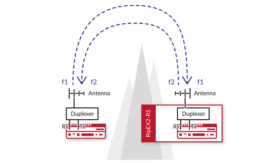
Full duplex (simultaneous Rx and Tx) on two frequencies for p-t-p (RipEX2) ● Half duplex (Rx and Tx switching) either on one or two frequencies (RipEX, RipEX2, RipEX2e)
Use our calculator to get an idea of the response times and throughput for your application in the RipEX network
DEVICE
Open casing tamper detection – FIPS 140-2 security level 2 ● Only RipEX2, RipEX2e
Digitally signed FW
Data integrity – FW is encrypted with a symmetric cypher ● Data authenticity – symmetric cypher is digitally signed by an asymmetric cypher ● Only RipEX2, RipEX2e
Secured FW upgrade
FW upgrade will only be accepted if it is digitally signed by RACOM
Secure boot
Device fully boots only when FW from RACOM is used
Physical port disable
Each physical interface (ETH’s, COM’s, USB, SFP…) can be individually enabled / disabled
Digital input which can be connected e.g. to cabinet door
MANAGEMENT
Web interface ● API interface (RipEX2, RipEX2e) ● SSL (X.509) certificate ● Possibility of own SSL certificate
Used for Fast remote access ● Command Line Interface (only RipEX)
Logical port disable
Each Logical port (HTTPS, SSH, SNMP…) or Virtual interface (Terminal server…) can be individually enabled / disabled
v1, v2c, v3 ● Any SNMP based NMS Software can be used ● Application note
ACCESS CONTROL
Role-based access control ● RipEX2, RipEX2e: 4 levels (Guest – read only, Tech – configuration excluding security, Sectech – Tech + security, Admin – full access); Max. No of user accounts (all levels together) is 100 ● RipEX: 2 levels (Guest – read only, Admin – full access); 2 users per level
Failed login alert ● Complexity (configurable) ● Timeout of inactivity (configurable) ● Lockout (after each failed attempt, the time for the next possible login is gradually extended up to 15 min.) ● Only RipEX2, RipEX2e
Centralized management of user access accounts from a remote authentication server ● Locally stored accounts are still available ● Only RipEX2, RipEX2e
DATA SECURITY
AES256-CCM encryption ● NIST SP 800-38C ● RFC 6655 ● Replay attack protection (25B control block: 13B nonce + 12B tag) ● Either own or randomly generated cryptographic key ● Periodic automatic exchange of randomly generated keys without interrupting user traffic
Encrypted end-to-end p-t-p tunnel ● All standard Linux features ● Data-origin authentication ● Data integrity control (MD5, SHA 1, 256, 384, 512…) ● Data encryption (3DES, AES128, 192, 256…) ● Forward secrecy Diffie-Hellman groups ● Periodic cryptographic keys Exchange (IKEv1, IKEv2) ● Post-quantum Pre-shared Key (PPK) ● AEAD ciphers ● Application note
Encrypted end-to-end p-t-mp tunnel ● RipEX2 as OpenVPN server(s) or OpenVPN client(s), 4 parallel instances in any combination ● One RipEX2 unit connects up to 30 clients ● Data integrity control (SHA256, SHA3-512, MD5…) ● Data encryption (AES256, ARIA, CAMELLIA…) ● Data compression (LZO, LZ4v2…– on/off, asymetric mode)
Keys and certificates are saved independently from unit configuration ● They can be uploaded or generated directly in the unit using high-entropy random number generators and updated independently ● Used by Radio channel encryption (AES256), IPsec, OpenVPN, Authentication of Remote access, Web server, FW distribution
Fully featured standard stateful Linux firewall ● Layer 2 – MAC, Layer 3 – IP, Layer 4 – TCP/UDP ● Any firewall rule can be logged in the Event Log ● All unwanted traffic is blocked at the network input
DEVICE
3 years warranty standard, optionally longer
Industrial design
Rugged die-cast aluminum case ● Conformal coating of PCBs for Harsh environment ● No adjustable components ● No moving parts ● Heavy-duty industrial components sourced exclusively from manufactures or authorized dealers
MTBF
Mean Time Between Failure > 100 years
Surge protection
Improved built-in RF surge protection ● External coaxial surge protection on the cabinet input is not mandatory ● Only RipEX2, RipEX2e
Atex II 3G Ex ic IIA T4 Gc ● IEC 60079-0
Seismic qualification
EN 60068-2-27
Power substation
EN 61850-3
Redundancy
RipEX-HS Master Station ● Hot standby ● 1+1 redundant ● Fully monitored ● Automatic failover ● Hot swappable ● Suitable for Central sites, Repeaters or Critical remotes where single point of failure is not tolerated
RADIO CHANNEL
ACM
(RipEX2)
Adaptive Coding and Modulation ● Automatically adjusts FEC and modulation according to real-time signal and channel conditions ● Maximises throughput, reliability and stability by dynamically adapting to interference, fading and environmental changes ● Hassle-free installation – no manual tuning or safety margins required ● More & Video
Three protocols on radio channel optimized for different applications ● Widely configurable – Packet acknowledgement, Number of retries…
Data integrity
Forward Error Correction ● Interleaving ● Proprietary data compression ● CRC32 data integrity control ● Proprietary protocol with packet acknowledgement
Different Modulation (Data speed), FEC, Packet anowledgement and Number of retries are possible to set for individual radio links from each unit
Private frequency
Licensed => Predictability, Non-shared operation ● Guaranteed capacity and Quality of Service ● Fully under the user’s control
CONNECTIVITY
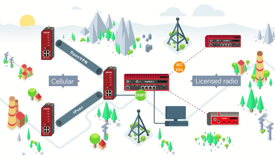
Radio and Cellular technologies (or any IP network) are combined into one network, utilising the best features of each ● One technology can be used as back-up for the other
Automatic failover to an alternative path ● Alternative path(s) can be on Radio channel or Cellular or any IP network
Native IP router
Each individual interface like Radio, ETH‘s and Cellular have their own IP/Mask, while COM ports are routed in the standard way – messages to them can be delivered to an IP address of any interface as UDP datagrams with the selected UDP port numbers.
Transparent protocol on the Radio channel ● Packets received on any interface (ETH, COM) are broadcast to the respective interfaces on all units in the network. Packets received on COM are broadcast to all COM’s at all remote sites, allowing you to connect more RTU’s to each remote unit.
Flexible or Base driven protocol on Radio channel ● Packets are addressed, routed and acknowledged
Ethernet ports can be combined as one or more Switch(es) with routing capabilities among them
Multiple Ethernet subnets (aliases) identified by its IP/Mask can be defined within each Ethernet interface
Each interface (Radio, Cellular, Ethernet…) has its own IP/Mask ● Mesh network over-the-air ● Direct peer-to-peer communication (not necessarily via the base station) ● Standard IP routing even on Radio channel ● Metric for each route
Routing tables are not needed at all ● RipEX2 is the only radio modem on the market which offer IP based full-featured Dynamic routing optimized for narrowband Radio channel ● See details
Automatic switchover between main and several backup links with priorities ● Automatic checking of the functionality of backup links and switching back to the higher priority link when it is restored ● IPsec tunnels can be bound to specific links via the Peer ID parameter, so that they are also swapped
PPP protocol over Ethernet ● Typically used for connection to Internet Service Provide over fixed line while Cellular network is a backup ● Client only ● Allows wide configuration of data speed, data volumes etc.
802.1Q ● ‘Unlimited‘ number of VLAN (1-4096) ● Any number of VLANs can be assigned to Subnets ● RipEX management can be done over separate VLAN ● Application note
Non encrypted end-to-end tunnel ● Encapsulates any network layer protocol inside virtual point-to-point link ● Application note
Source and destination (IP/Mask/Port) translation supported ● Suitable for cases, when all RTU’s in network have got the same IP address ● Application note
8 priority levels (all interfaces, Radio included) based on protocol (TCP, UDP…) and source and destination (IP/Mask/Port) ● 802.1p and DiffServ (DSCP) supported ● Guaranteed bandwidth for critical traffic ● Application note
TCP proxy (RipEX)
ARP proxy (RipEX)
RipEX can mimic any IP address (typ. RTU behind the Radio channel) ● Suitable in case when RTU’s in the network are without routing capabilities (the default gateway cannot be configured) and they are within the same subnet ● In the case of RipEX2, GRE tunnel can be used instead of an ARP proxy ● Application note ● Video
Unique options
RADIO PROTOCOLS
Only one protocol on Radio channel is not enough, because different applications have different requirements for Collision management, Response time, Jitter, Latency and Communication topology.
Only RipEX provides three different protocols which are optimized for different applications, from legacy serial to modern TCP/IP such as IEC104, making the network reliable and stable, even with a high number of RTU’s.
| Base driven | Flexible | Transparent | |
| Topology | Star | Tree | Any |
| Repeaters | One on each link | Unlimited | 1-2 possible |
| Device mode | Router | Router | Bridge |
| Application | Any, TCP/IP optimized | Any | Master-slave |
| Base stations | Dedicated | Available | Available |
| Collisions | Impossible | Managed | Unmanaged |
| Packet acknowledgement | Yes | Yes | No |
Optimized for TCP/IP ● Star topology ● Repeaters supported ● No collisions ● All traffic is fully managed by Base station ● Up to 255 remotes under one Base station ● Static or Dynamic routing ● Fair distribution of channel capacity among all remotes ● Stable response times with minimum jitter ● Info sheet ● Application note – Base driven protocol ● Application note – Address planning ● Video
Tree topology ● Unlimited number of repeaters and branches ● Full Mesh – any unit communicates directly with any other ● No extra base stations ● Any unit simultaneously a repeater ● Static or Dynamic routing ● Managed collisions ● (Multi) polling and report-by-exception concurrently ● Info sheet ● Application note – Address planning ● Application note – Radio channel access ● Video
Star topology ● Repeaters supported ● Fully transparent ● Unmanaged collisions ● Master-slave polling applications ● Minimum latency – all received packets are immediately broadcast to the Radio channel ● Video
SCADA PROTOCOLS
Serial
Unique SW drivers map Serial SCADA protocol addresses to RipEX IP addresses and reduce the amount of data that is transferred over-the-air ● Modbus ● IEC101 ● DNP3 ● PR2000 ● Comli ● DF1 ● Async Link ● PPP ● Siemens 3964(R) ● SAIA S-BUS ● UNI ● MARS-A ● RDS ● Transparent ● C24, RP570, Slip, Cactus, Profibus (RipEX) ● Application note – Modbus ● Application note – UNI
Ethernet
TCP (UDP) protocols (e.g. IEC104, DNP3/TCP, etc.) can be handled transparently or using Terminal server or TCP proxy (RipEX only) ● Embedded Modbus RTU / Modbus TCP converter
DYNAMIC ROUTING
Dynamic routing
(RipEX2, RipEX2e)
Routing tables are not needed at all ● On/Off for each interface (Radio, Cellular, ETH’s) and VLAN ● Units broadcast to their neighbors where they can route and based on that the gateway with the best metrics is selected ● The next packet to the same destination can be routed via different gateway
Babel
(RipEX2, RipEX2e)
Optimized for narrowband Radio channel ● Different algorithms for wired and wireless interfaces ● Minimum overhead ● OSPF based ● Application note ● Video
OSPF
(RipEX2, RipEX2e)
Standard OSPF protocol which is designed to exchange routing and reachability information inside autonomous systems is implemented ● Typically used for RipEX backhaul network routing ● RFC 2328
BGP
(RipEX2, RipEX2e)
Standard BGP protocol which is designed to exchange routing and reachability information among autonomous systems is implemented ● RFC 4271
Nomadic mode
(RipEX)
Automatic routing between Nomadic Centre and Remotes ● Any existing unit can be configured as Nomadic Base ● Nomadic Remotes automatically connect to the best available Nomadic Base ● Network expansion without changes in Routing tables ● Portability – Nomadic Remotes can be transferred from one Base to another ● Application note
BACKUP ROUTES
Backup routes
Backup routes feature significantly increases network reliability by automatically switching to an alternative path in the case of a failure ● Alternative paths can be on any interface (Radio, Cellular, ETH’s)
Link management
(RipEX2, RipEX2e)
Routing rules are static ● Several backup links with priorities ● Backup links functionality is continuously tested (Test period, Repeat period, Reply timeout, Passes, Retries…) ● Switching back to the higher priority link when it is restored ● IPsec tunnels can be bound to particular links via Peer ID parameter so they are also swapped respectively
Dynamic switching
(RipEX2, RipEX2e)
Dynamic alternative paths between any two IP devices (RipEX, Cisco, …) ● Dynamic routing (as described above) is used ● Application note
Proprietary solutions
(RipEX)
Alternative paths are static and always between two RipEX IP addresses, even behind a repeater(s) or IP network ● Several backup paths with priorities ● Backup paths functionality is continuously tested (Packet losses, Weak RSS…) ● Application note ● Video
Hybrid networks
RipEX Radio modems and M!DGE Cellular routers interconnected within a single network and with a single interface to the application ● No additional hardware required ● One technology can be used as backup for the other ● RipEX2 with mPCI Cellular module enables one box solution ● Same SW protocol drivers and logic on all interfaces of all devices ● Info sheet
| Network characteristics | |
| Radio | Cellular |
| Private network – completely under user’s control | Public network – 3rd party dependency Make use of existing infrastructure |
| Single user – guaranteed capacity and behaviour | Multi users can affect capacity and behaviour |
| Licensed frequency – guaranteed quality of service | Public networks – quality of service not guaranteed |
| Higher investment, guaranteed running fees paid to government | Lower investment, unpredictable running fees paid to service provider |
| Mission critical real-time applications | Non-mission critical applications |
Migration solution
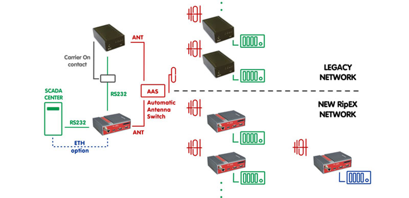
It is used in case of legacy radio network modernization or when simultaneous use of two radio networks is required ● Info sheet ● Application note
Customer benefits
Standard RipEX units used – no expensive temporary migration HW required ● No network outage during migration ● No time limits for legacy and new RipEX networks co-existence ● Migration as part of regular maintenance ● Gradual one by one replacement
Technical features
No changes to legacy network required ● Both legacy and new RipEX networks can use the same frequency ● Both legacy and new radios can share a common antenna ● Automatic Antenna Switch automatically manages antenna switching ● HW contact for ‘Carrier On’ legacy base station transmissions supported ● RipEX routing table manages traffic for both networks ● More
Features
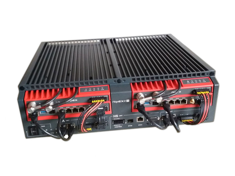
Two standard hot-swappable RipEX2 units + controller in 19″ rack 3U chassis ● Two independent power supplies, each for one unit ● 1+1 redundant ● Software-free controller ● Automatic switch-over based on DI/DO interfaces of the units ● Virtual MAC addresses identical in both units ● Switch-over time < 5 s ● Pictures
Both units are booted, only one is active ● Interfaces (ETH, COM, (SFP), Radio) of the 2nd unit are disconnected ● When the status of the active unit changes to “down” (any controlled value exceeds the set limit), the controller automatically switches all interfaces from the 1st unit to the 2nd unit and it takes over all functions ● SNMP trap with each switch-over can be sent
● Auto – primary active is RipEX “A”, when it fails, controller automatically switches-over to RipEX “B”
● Auto toggle – the same as “Auto“, in addition after set time controller automatically switches-over to RipEX “B” for set period in order to confirm that RipEX “B” is fully ready-to-operate
● A – only RipEX “A” is active and controller will never switch to RipEX “B”
● B – only RipEX “B” is active and controller will never switch to RipEX “A”
Standard RipEX units mean their standard diagnostics ● Hot-standby parameters are configured in RipEX unit(s) ● Four HW alarm outputs: Standard HW alarms of units “A” and “B”, Controller alarm – indicates controller problem, Switch alarm – Notifies of switch-over from active to backup unit ● Two HW inputs can be used in “Auto” mode to set unit “A” or “B” as primary
Antenna – all possibilities for either switched or redundant antennas ● Powering – four options: 100 – 240 VAC; 36 – 60 VDC, positive grounding possible; 18 – 30 VDC, positive grounding possible; 10 – 30 VDC ● Ordering information
Each device is supplied with all the necessary accessories for mounting in a 19″ rack
Features
Transparent L2 Bridge ● Up to 1.7 Mb/s @ 300 kHz in both directions simultaneously ● Minimum latency ● Long distances (5-50 km) when Line of sight is not required ● Frequency pair to be used ● Either external or internal duplexer ● All RipEX2 features supported ● Video
Use cases
Power distribution ● GOOSE messaging (IEC 61850) ● SEL Mirrored Bits (relay-to-relay) ● AMI/AMR concentrators backbone ● Interconnection of DMR base stations…
Mounting
Common surrounding temperature – DIN rail or shelf in a 19″ rack ● High surrounding temperature – it is recommended to use 19″ rack chassis RipEX2-RS (1x RipEX2, 1x Power supply, 1x Internal Duplexer (optional) or RipEX2-HS (Redundant solution, 2x RipEX2, 2x Power supply, 1x Internal Duplexer (optional)
Other details
Management access
Web interface
API interface
(RipEX2, RipEX2e)
Application Programming Interface ● Unit can be managed by external application ● Full access to configuration and diagnostics ● Detail description on request
CLI interface
(RipEX)
Command Line Interface ● Via SSH
Only required data from remote unit are transferred over-the-air ● HTML page is provided from the local unit ● Secured communication using RSA key
Automatic FW upgrade ● SW Keys upload, Configuration backup / restore, SSL certificate upload, Technical support package download (only RipEX)
All documentation is publicly available ● Datasheets ● User manuals ● Info sheets ● Application notes
Technical presentations ● Tutorials ● Technical guides ● FW upgrades ● Webinars
ICMP Ping ● RSS Ping with Data Quality (RipEX) or MSE (RipEX2, RipEX2e)
Detailed statistics for all interfaces ● Rx/Tx packets, Rx/Tx bytes, Total, Repeats, Lost, Rejected… ● Historical and Differential data
Real time / Save-to-file detailed analysis of all interfaces
Proprietary NMS is not required ● Any SNMP based NMS Software can be used ● Free open-source Zabbix is recommended ● Test live demo Zabbix here (customer / RacomDemo1234) ● SNMP notification when specific Event is triggered ● Application note
Eight levels of severity for each event ● SNMP notifications ● SMS ● HW alarm outputs (AO, DO1, DO2) activation
Logging of events on a remote server ● RFC5424
Quick overview about unit sections (Device, Interfaces, Security, Routing…) ● Malfunctioning antenna ● FW versions ● Serial numbers ● Alarms…
HW alarm input ● HW alarm output
Both, SMS commands and SMS notifications are supported ● SMS password for SMS commands ● Only when extension mPCIe Cellular module is used
File with advanced information for RACOM’s technical support
The same HW for base, repeater or remote stations minimizes spare parts and allows easy network reconfiguration ● FSK and QAM modulations within one box ● Different models ● 19″ rack chassis ● More
Solar ready
Low power consumption ● RipEX2: 8 W / Rx, 12 – 40 W / Tx ● RipEX: 5 W / Rx, 13 – 30 W / Tx
Wake up by internal RTC (RipEX2, RipEX2e) or by Sleep digital input (RipEX2, RipEX2e, RipEX)
Save mode
(RipEX)
Wake up by a received packet from Radio channel or by Sleep digital input
FW 2.2.6.0
- October 2025
- ACM – Adaptive Coding and Modulation
- Maximizes throughput and link stability under degraded conditions
- Automatically adjusts coding (FEC) and modulation according to real-time signal quality
- Extremely fast – adapts seamlessly without data loss
- Firewall rules logging
- Any firewall rule can now be logged in the Event Log
- Very useful for detecting potential software or network attacks
- New Cellular modules supported (LTE Cat M1/NB1/NB2)
- Telit ME310G1-W2 – 410 / 450 MHz, Anatel, EU certified, order code var. ‘R’ (replaces ‘M’)
- Telit ME310G1-WW – FCC, APAC certified, order code var. ‘S’ (replaces ‘O’)
- Release notes
FW 2.2.4.0
- Login credentials improved
- No more default values
- Unique credentilas must be created for the first login
- Strong password level required
- L3 firewall upgrade
- Source and destination addresses filtering
- Output interface selection
- IPsec extensions
- Transport mode
- Traffic selectors – policy filters integrated with L3 firewall
- Wi-Fi now supports hidden SSIDs and automatic channel selection
- Event log now shows active configuration at the time of each event
- Advanced menu links now contain search strings
- Release notes
Latest Radio and Cellular Routers in SCADA
You will learn about ‘The Latest Trends in Wireless Communication in SCADA Networks’ and how RACOM‘s products meet them. We talk about real-life examples as well as hybrid networks that combine different types of data communication. There are also examples of using RipEX2e and M!DGE3, which were new at the time of the webinar.
Next Generation IP Radio Modems
The latest generation of VHF/UHF radio modems for private networks can do things you wouldn’t expect. Today they are native IP devices, data rates and overall network throughput have increased dramatically. Standard static or dynamic IP routing can be set up on the radio channel including backup routes. Various protocols optimized for different applications are available on the radio channel, modems meet the latest security requirements etc.
MR400 Radio SCADA Network Upgrade to RipEX2
MR400, an older generation of RACOM radio modems produced since 2005, is nearing its end-of-life. You will learn how to upgrade your legacy network smoothly to incorporate our most recent radio modem RipEX2 and what advantages and new possibilities you will get. Real-life stories of successful migration from MR400 to RipEX2 are also presented. At the end of the webinar there is an online Q&A session.
Specifications
| RipEX2 | RipEX2e | RipEX | |
| Max. Speed | 1.7 Mb/s @ 256QAM |
250 kb/s @ 64QAM |
166 kb/s @ 16DEQAM |
| Speed @ 25 kHz | 167 kb/s | 125 kb/s | 83 kb/s |
| Channel size | 6.25 – 300 kHz | 6.25 – 50 kHz | 6.25 – 50 kHz |
| Interfaces | 4×ETH, 1×SFP, 2×COM, 1×USB | 2×ETH,2×COM, 1×USB | 1×ETH,2×COM, 1×USB |
| mPCIe | Yes | No | No |
| Full duplex | Yes | No | No |
| Fully Redundant Hot Standby Master Station | Yes | No | Yes |
| Management Access | 4 levels | 4 levels | 2 levels |
| IPsec | Yes | Yes | Yes |
| RADIUS | Yes | Yes | No |
| Radio parameters | RipEX2 | RipEX2e | ||||
| Frequency bands | 135 – 175; 215 - 240 MHz
285 – 335; 335 – 400 MHz 400 – 470; 450 – 520 MHz 803 – 897; 860 – 960 MHz |
|||||
| Channel spacing | 6.25; 12.5; 25; 50; 100; 150; 200; 250; 300 kHz | 6.25; 12.5; 25; 50 kHz | ||||
| Frequency stability | ±0.5 ppm see details | |||||
| Modulation | QAM: 256QAM; 64QAM; 16DEQAM; D8PSK; π/4DQPSK;
DPSK FSK: 4CPFSK; 2CPFSK, see details |
QAM: 64QAM; 16DEQAM; D8PSK; π/4DQPSK;
DPSK FSK: 4CPFSK; 2CPFSK, see details |
||||
| FEC (Forward Error Correction) | 2/3; 3/4; 5/6; Off
Trellis code with Viterbi soft-decoder |
|||||
| Gross data rate (data speed) 1) | Channel spacing
[kHz] |
Gross data rate
(modulation rate)
[kb/s] |
Channel spacing
[kHz] |
Gross data rate
(modulation rate)
[kb/s] |
||
| 6.25 | 35 | 6.25 | 26 | |||
| 12.5 | 83 | 12.5 | 63 | |||
| 25 | 167 | 25 | 125 | |||
| 50 | 333 | 50 | 250 | |||
| 100 | 555 | |||||
| 150 | 925 | |||||
| 200 | 1111 | |||||
| 250 2) | 1389 | |||||
| 300 2) | 1736 | |||||
| Transmitter | ||||||
| RF Output power | QAM: 0.1 – 5.0 W (20 – 37
dBm) RMS in 1dB step 3)
FSK: 0.1 – 10 W (20 – 40 dBm) in 1dB step see details |
|||||
| Duty cycle | Continuous | |||||
| Rx to Tx Time | < 2 ms @ 6.25 kHz
channel < 1.0 ms @ 12.5 kHz channel < 0.7 ms @ 25 kHz channel |
|||||
| Spurious Emissions (Conducted) | < -36 dBm | |||||
| Radiated Spurious Emissions | < -36 dBm | |||||
| Adjacent channel power | < -60 dBc | |||||
| Transient adjacent channel power | < -60 dBc | |||||
| Receiver | ||||||
| Anti-aliasing Selectivity | 56 kHz
@ -3 dB
BW applicable for 6.25; 12.5; 25 kHz
500 kHz @ -3 dB BW applicable for 50; 100; 150; 200; 250; 300 kHz |
56 kHz
@ -3 dB
BW applicable for 6.25; 12.5; 25 kHz
500 kHz @ -3 dB BW applicable for 50 kHz |
||||
| Tx to Rx Time | < 2 ms @ 6.25 kHz
channel < 1.0 ms @ 12.5 kHz channel < 0.7 ms @ 25 kHz channel |
|||||
| Maximum Receiver Input Power | 20 dBm (100 mW) | |||||
| Rx Spurious Emissions (Conducted) | < -57 dBm | |||||
| Radiated Spurious Emissions | < -57 dBm | |||||
| Blocking or desensitization | > -23 dBm
@ 1 MHz
> -19 dBm @ 2 MHz > -15 dBm @ 5 MHz > -13 dBm @ 10 MHz |
|||||
| Spurious response rejection | > 70 dB | |||||
| Technical parameters are subject to change without prior notification. | ||||||
| 1) | Network throughput varies and depends heavily on the data structure, optimization effectivity, protocol on Radio channel, network topology, signal budgets and many other parameters of the network. Practical tests are recommended. | |||||
| 2) | Available only in Bridge mode. | |||||
| 3) | Max peak envelope power (PEP) 10 W (40 dBm) . | |||||
| Electrical | RipEX2 | RipEX2e | |||
| Primary power | 10 to 30 VDC, negative GND | ||||
| Rx | 8.3 W @ 24 V, see details | ||||
| Tx | 12 – 55 W @ 24 V, see details | ||||
| Sleep mode | 0.01 W | ||||
| Interfaces | |||||
| Ethernet | 10/100/1000Base-T Auto MDI/MDIX | 4× RJ45 | 10/100/1000Base-T Auto MDI/MDIX | 2× RJ45 | |
| SFP | 10/100/1000Base-T or 1000Base-SX or 1000Base-LX user exchangeable SFP with max. power consumption 1.25 W |
1× SFP | No SFP | ||
| COM | RS232 / RS485 SW configurable | DB9F | |||
| 600 b/s – 2 Mb/s | |||||
| COM2 RipEX2e, RipEX2 var. F and O | RS232 | DB9F (COM1, COM2) | |||
| 600 b/s – 2 Mb/s | |||||
| COM2, COM3 Extension module ‘C’: Not available for RipEX2e, RipEX2 var. F and O |
2× RS232 |
RJ45 | |||
| COM2: 300 b/s – 2
Mb/s; COM3: 2.4 kb/s – 921.6 kb/s |
|||||
| USB | USB 3.0 | Host A | |||
| Antenna | 50 Ω SW configurable 1× Tx / Rx or 1× Rx + 1× Tx |
2× TNC female | 50 Ω 1× Tx / Rx |
1× TNC female | |
| Inputs/Outputs | 1× HW alarm input
1× HW alarm output 1× Sleep input |
Power connector |
|||
| 2× DI, 2× DO, 1× diffDI
not available when Extension module 'C' (COM ports) is used |
RJ45 | Not available | |||
| Indication LEDs | |||
| LED panel | 5× tri-color status LEDs (SYS, EXT, RX, TX, COM) | ||
| ETH | 4× RJ45 (Link and Activity LEDs), 1× SFP (Status LED) | ||
| Environmental | |||
| IP Code (Ingress Protection) | IP41, IP42, IP52 - see details | ||
| MTBF (Mean Time Between Failure) | > 900 000 hours (> 100 years) | ||
| Operating temperature | −40 to +70 °C ( −40 to +158 °F) 4) | ||
| Operating humidity | 5 to 95 % non-condensing | ||
| Storage | −40 to +85 °C ( −40 to +185 °F) / 5 to 95 % non-condensing | ||
| Mechanical | |||
| Casing | Rugged die-cast aluminium | ||
| Dimensions |
H×W×D: 60×185×125.5 mm (2.34×7.2×4.94 in) |
||
| Weight |
1.55 kg (3.4 lbs) |
||
| Mounting | DIN rail, L-bracket,
Flat-bracket, 19" Rack chassis
see details |
||
| SW | |||
| Operating modes | Bridge / Router | ||
| Radio channel protocols | Transparent @
Bridge Base driven, Flexible @ Router (RipEX2e does not support Base station in Base driven) see details |
||
| User protocols on COM | DNP3, DF1, IEC101, Modbus RTU, PR2000, RDS, Siemens 3964(R), COMLI, SAIA S-bus, Mars-A, PPP, UNI, Async Link | ||
| User protocols on Ethernet | Modbus TCP, IEC104, DNP3 TCP, Comli TCP, Terminal server… | ||
| Serial to IP convertors | DNP3 / DNP3 TCP, Modbus RTU / Modbus TCP | ||
| Routing (both, Radio and Ethernet) | Static, Dynamic - Babel, OSPF, BGP, Link management | ||
| QoS | 8 levels on all interfaces | ||
| Protocol on Radio channel | |||
| Multi master applications | Yes | ||
| Report by exception | Yes | ||
| Collision Avoidance Capability | Yes | ||
| Remote to Remote communication | Yes | ||
| Repeaters | Store-and-forward Every unit Unlimited number |
||
| Data integrity control | CRC 32 | ||
| Optimization | Intelligent payload data and header (Eth / IP / TCP / UDP) compression | ||
| Security | |||
| Management | HTTPS (Web Interface or Application Programming Interface) | ||
| Role-based access control (RBAC) | 4 levels (Guest, Tech, SecTech, Admin) | ||
| Wi-Fi management access | WPA2-PSK secured | ||
| Encryption | AES256-CCM | ||
| VPN | IPsec, OpenVPN, GRE | ||
| VLAN | IEEE 802.1Q (tagging), Q-in-Q for Transparent mode | ||
| AAA protocol | RADIUS | ||
| Firewall | Layer 2 - MAC, Layer 3 - IP, Layer 4 - TCP/UDP | ||
| FW | Digitally signed | ||
| HW tamper | Case opening evidence | ||
| 4) | When full-duplex with full power (40 dBm PEP) and the surrounding temperature above + 60°C the external passive cooler should be used (e.g. RipEX2-RS 19" Rack chassis). | ||
| Diagnostic and Management | |
| Link testing | ICMP ping, RSS ping |
| Status information | User interfaces |
| Statistics |
Historical and differential statistics for Rx / Tx Packets on all user
interfaces (ETH 1-5, COM 1-3, TS 1-5) and Radio interface - for individual
connections. |
| Statistics history | Several weeks |
| Event log | Events filtered by time, severity, user, remote IP address and type of event |
| SNMP | SNMPv1, SNMPv2c, SNMPv3 Trap / Inform alarms generation as per settings |
| NTP | Client / Server |
| Monitoring | Real time analysis of all interfaces (RADIO, ETH 1-5 , COM 1-3, TS 1-5) and internal interfaces between software modules, see details |
| Standards | |
| CE | RED; RoHS; WEEE |
| FCC, IC | FCC Part 90, IC RSS-119 |
| Spectrum | ETSI EN 302 561 V2.1.1 ETSI EN 300 113 V2.2.1 |
| EMC (electromagnetic compatibility) |
ETSI EN 301 489-1 V2.2.3 ETSI EN 301 489-5 V3.2.1 EN 61850-3:2014 |
| Product safety | EN 62368-1:2014 + A11:2017 |
| Cybersecurity | EN 18031-1:2024 |
| RF health safety | EN 62311:2008 |
| Electric power substations environment |
IEEE 1613:2009 IEEE 1613.1:2013 EN 61850-3:2014 |
| Hazardous locations | EN 60079-0:2012 EN 60079-11:2012 |
| Environmental | EN 61850-3: 2014 |
| Vibration & shock |
EN 60068-2-6:2008 |
| Seismic qualification | EN 60068-2-27:2010 |
| IP rating | EN 60529:1993 + A1:2001 + A2:2014 |
| Optional interfaces (not applicable for RipEX2e) | ||
|
Extension module 'G' |
Active antenna 3.3 VDC SMA female (EXT on front panel) | |
| 72-channel u-blox M8 engine GPS/QZSS L1 C/A, GLONASS L10F, BeiDou B1I, Galileo E1B/C, SBAS L1 C/A: WAAS, EGNOS, MSAS, GAGAN | ||
|
Extension module 'C' |
COM2: RS232 - 5 pin (RxD, TxD, GND, RTS, CTS) 300 b/s to 2 Mb/s COM3: RS232 - 3 pin (RxD, TxD, GND) 2.4 kb/s to 921.6 kb/s RJ45 (DI/DO on front panel) |
|
|
Extension module 'W', 'M', 'O', 'R', 'S'
|
see details | |
|
Extension module 'F'
|
IEEE 802.11a/b/g/n/ac 2x2 MIMO 20 MHz / 40 MHz for 2.4 GHz 20 MHz / 40 MHz / 80 MHz for 5 GHz WPA/WPA2 PSK WPA3-SAE AES/TKIP hardware encryption Output power up to 16 dBm EmWicon WMX6218 - FCC ID 2A3G3-WMX6218 |
|
| Radio parameters | RipEX2-HS | |
| The same as RipEX2 units used | ||
| Hot Standby | ||
| Switch-over time | < 2 s | |
| Electrical | ||
| Primary power | HW models | |
| 100 – 240 VAC, 50 – 60 Hz 36 – 60 VDC, positive grounding possible |
||
| 10 – 30 VDC 18 – 30 VDC, positive grounding possible |
||
| Individual power supply for each unit | ||
| Power consumption | HS own consumption typically <10 W (+ 1× Rx + 1× Rx/Tx of individual units) | |
| RipEX-HSB | No | |
| Interfaces | ||
| detail | ||
| Ethernet | 1× 10/100/1000 Base-T Auto MDI/MDIX, RJ45 | |
| SFP | 1× 10/100/1000Base-T/1000Base-SX/1000Base-LX | |
| COM 1 | RS232/RS485 SW configurable, DB9F 300 bps – 1 Mbps |
|
| COM 2 | No | |
| USB | USB 3.0 / Host A, for each RipEX2 unit | |
| Antenna | N-female(s) / 50 Ohms | |
| HW models | ||
| Environmental | ||
| IP Code (Ingress Protection) | IP30 | |
| MTBF (Mean Time Between Failure) | > 900 000 (> 100 years) | |
| Operating temperature | –40 to +70 °C (-40 to +158 °F) | |
| Humidity | 5 to 95% non-condensing | |
| Storage | −40 to +85 °C (−40 to +185 °F) / 5 to 95 % non-condensing | |
| Internal fans | No | |
| Mechanical | ||
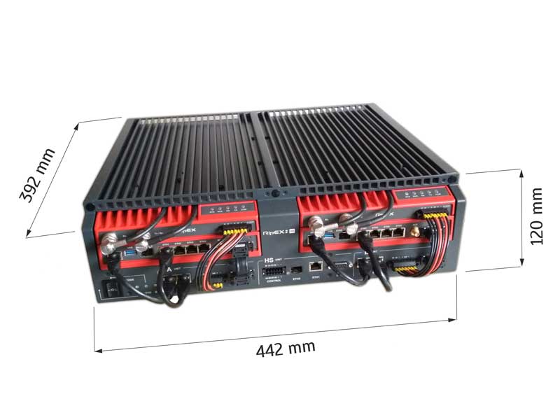
| Dimensions | 19″ rack 3U 442 W × 392D × 120H mm (17.40 × 15.43 × 4.72 in) |
|
| Weight | 8.9 kg (19.6 lbs), RipEX2 unit exl. 12.1 kg (26.7 lbs), RipEX2 unit incl. |
|
| Diagnostics and Management | ||
| Same tools as with standard RipEX units used | ||
| LED panels | Standard RipEX2 LED panel: SYS, AUX, RX, TX, COM HS controller: A, AUTO, B, SFP |
|
| HW Alarm outputs | RipEX2 A, RipEX2 B, Controller, General alarm | |
| Standards | ||
| CE, FCC | ||
| Radio parameters | ||||||||||||||
| Frequency bands | 135 – 154; 154 – 174 MHz 215 – 240 MHz 300 – 320; 320 – 340; 340 – 360 MHz 368 – 400; 400 – 432; 432 – 470 MHz 470 – 512 MHz 928 – 960 MHz see details |
|||||||||||||
| Channel spacing | 6.25; 12.5; 25; 50 kHz 1) | |||||||||||||
| Frequency stability | ±1.0 ppm | |||||||||||||
| Modulation | QAM (linear): 16DEQAM; D8PSK; π/4DQPSK; DPSK | |||||||||||||
| FSK (exponential): 4CPFSK; 2CPFSK | see details | |||||||||||||
| FEC (Forward Error Correction) | On/Off, ¾ Trellis code with Viterbi soft-decoder | |||||||||||||
| Gross data rate (data speed) 2) |
|
|||||||||||||
| Transmitter | ||||||||||||||
| RF Output power | QAM: 0.5 – 2 W
3) FSK: 0.1 – 10 W 4) see details |
|||||||||||||
| Duty cycle | Continuous | |||||||||||||
| Rx to Tx Time | < 1.5 ms | |||||||||||||
| Intermodulation Attenuation | > 40 dB | |||||||||||||
| Spurious Emissions (Conducted) | < -36 dBm | |||||||||||||
| Radiated Spurious Emissions | < -36 dBm | |||||||||||||
| Adjacent channel power | < -60 dBc | |||||||||||||
| Transient adjacent channel power | < -60 dBc | |||||||||||||
| Receiver | ||||||||||||||
| Sensitivity | -113 dBm (12.5 kHz, 2CPFSK, BER 10-6, 3/4 FEC, see details | |||||||||||||
| Anti-aliasing Selectivity | 50 kHz @ -3 dB BW | |||||||||||||
| Tx to Rx Time | < 1.5 ms | |||||||||||||
| Maximum Receiver Input Power | 20 dBm (100 mW) | |||||||||||||
| Rx Spurious Emissions (Conducted) | < -57 dBm | |||||||||||||
| Radiated Spurious Emissions | < -57 dBm | |||||||||||||
| Blocking or desensitization | see details | |||||||||||||
| Spurious response rejection | > 70 dB | |||||||||||||
| 1) | 50 kHz channel spacing is HW dependent, versions before 2014 didn´t support it. 6.25 kHz channel spacing is not available for RipEX-928. | |||||||||||||
| 2) | Network throughput varies and depends heavily on the data structure, optimization effectivity, protocol on Radio channel, network topology, signal budgets and many other parameters of the network. Practical tests are recommended. | |||||||||||||
| 3) | Max peak envelope power (PEP) 7.0 W | |||||||||||||
| 4) | For output power 10 W it is recommended to use input power above 11 VDC. | |||||||||||||
| RipEX-470, RipEX-928 - max. RF Output power 8 W. | ||||||||||||||
| Electrical | ||||
| Primary power | 10 to 30 VDC, negative GND | |||
| Rx | 5 W / 13.8 V; 4.8 W / 24 V; (Radio part < 2 W) | |||
| Tx | 13 – 40 W, see details | |||
| Sleep mode | 0.1 W | |||
| Save mode | 2 W | |||
| Interfaces | ||||
| Ethernet | 10/100 Base-T Auto MDI/MDIX | RJ45 | ||
| COM1 | RS232 | DB9F | ||
| 300 – 115 200 b/s | ||||
| COM2 | RS232/RS485 SW configurable | DB9F | ||
| 300 – 115 200 b/s | ||||
| USB | USB 1.1 | Host A | ||
| Antenna | 50 Ω | TNC female | ||
| Inputs/Outputs | 1x HW alarm input 1x HW alarm output 1x Sleep input |
Power connector | ||
| Indication LEDs | |||
| LED panel | 7× tri-color status LEDs (Power, ETH, COM1, COM2, Rx, Tx, Status) |
||
| Environmental | |||
| IP Code (Ingress Protection) | IP40, (IP51 - see details) | ||
| MTBF (Mean Time Between Failure) | > 900 000 hours (> 100 years) | ||
| Hazardous lodations | Ex II 3G Ex ic IIC T4 Gc | ||
| Operating temperature | −40 to +70 °C (−40 to +158 °F) | ||
| Operating humidity | 5 to 95 % non-condensing | ||
| Storage | −40 to +85 °C (−40 to +185 °F) / 5 to 95 % non-condensing | ||
| Mechanical | |||
| Casing | Rugged die-cast aluminium | ||
| Dimensions | H × W × D: 50 × 150 × 118 mm (1.97 × 5.9 × 4.65 in) | ||
| Weight | 1.1 kg (2.4 lbs) | ||
| Mounting | DIN rail, L-bracket, Flat-bracket, 19" Rack shelf | ||
| SW | |||
| Operating modes | Bridge / Router | ||
| Radio channel protocols | Transparent @ Bridge Base driven, Flexible @ Router see details |
||
| User protocols on COM |
Modbus, IEC101, DNP3, PR2000, UNI, Comli, DF1, RP570, Profibus, … |
||
| User protocols on Ethernet | Modbus TCP, IEC104, DNP3 TCP, Comli TCP,
Terminal server… |
||
| Serial to IP convertors | Modbus RTU / Modbus TCP, DNP3 / DNP3 TCP | ||
| Protocol on Radio channel | |||
| Multi master applications | Yes | ||
| Report by exception | Yes | ||
| Collision Avoidance Capability | Yes | ||
| Remote to Remote communication | Yes | ||
| Addressed & acknowledged serial SCADA protocols |
Yes | ||
| Data integrity control | CRC 32 | ||
| Optimization | Payload data and Ethernet / IP / TCP / UDP header compression, Packet flow on Radio channel optimization | ||
| Security | |||
| Management | HTTP, HTTPS (own certificate), SSH | ||
| Access accounts | 2 levels (Guest, Admin) | ||
| Encryption | AES256-CCM | ||
| VPN | IPsec, GRE | ||
| VLAN | IEEE 802.1Q (tagging), Q-in-Q for Transparent mode | ||
| Firewall | Layer 2 - MAC, Layer 3 - IP, Layer 4 - TCP/UDP | ||
| Diagnostic and Management | |||
| Radio link testing | Yes (ping with RSS, Data Quality, Homogeneity) | ||
| Watched values (Can be broadcast to neighbouring units. Received info displayed in Neighbours table) | Device - Ucc, Temp, PWR, VSWR, *HW Alarm
Input. Radio channel - *RSScom, *DQcom, TXLost [%] User interfaces - ETH (Rx/Tx), COM1 (Rx/Tx), COM2 (Rx/Tx) * not broadcast |
||
| Statistics | For Rx/Tx Packets on User interfaces (ETH, COM1, COM2) and for User data and Radio protocol (Repeats, Lost, ACK etc.) on Radio channel | ||
| Graphs | For Watched values and Statistics | ||
| History (Statistics, Neighbours, Graphs) |
20 periods (configurable, e.g. days) | ||
| SNMP | SNMPv1, SNMPv2c, SNMPv3 SNMP Traps or SNMP Informs generation for Watched values |
||
| NTP | Client, Server (synchronized from internal GPS) | ||
| Monitoring | Real time/Save to file analysis of all physical interfaces (RADIO, ETH, COM1, COM2) and some internal interfaces between software modules (e.g. Terminal servers, Modbus TCP server etc.) | ||
| Standards | |
| CE | RED, RoHS, WEEE |
| FCC, IC | FCC Part 90, Pending: IC RSS-119 |
| Spectrum | ETSI EN 302 561 V2.1.1:2017 ETSI EN 300 113 V2.2.1:2017 |
| EMC (electromagnetic compatibility) | ETSI EN 301 489-1 V2.1.1:2017 ETSI EN 301 489-5 V2.1.1:2017 IEC 1613:2009 Class 1 |
| Safety | EN 60950-1:2006, A11:2009, A1:2010, A1:2010, A12:2011, A2:2013 |
| SAR | EN 50385:2002 EN 50383ed.2:2011 |
| Vibration & shock | EN 61373:1999 EN 60068-2-6:2008 |
| Seismic qualification | IEC 980:1989 (seismic category 1a) |
| Hazardous locations | EN 60079-0:2012 EN 60079-11:2012 |
| IP rating | EN 60529:1993 + A1:2001 + A2:2014 |
Accessories
RACOM is a primary producer and therefore does not provide delivery of all available accessories for its products. This list contains tested accessories which RACOM is able to deliver together with RipEX units. Components are only held in limited quantities and the delivery date may therefore be affected by the need for subcontracting. If you require other accessories, please contact us or your supplier.
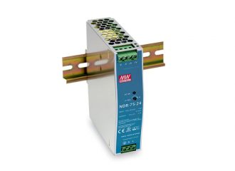
DC power supply, DIN rail
- Input 90-264 VAC, 127-370 VDC
- Output 12 VDC
- 75 W
- -20°C to +70°C
- Overload, Over voltage, Over temperature protections
- Direct DIN rail mounting
- Datasheet, Part No.: PWS-AC,DC/12VDC/75W2
- Replacement of PWS-AC,DC/12VDC/76W from VIII/2021
- Manufactured by MeanWell
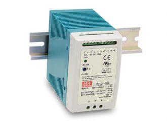
DC power supply, Battery charger
- Input 90 – 264 VAC, 127 – 370 VDC
- Output 13.8 VDC
- 97 W
- -30°C to +70°C
- Overload, Over voltage, Battery low protections
- Back-up battery charger
- Direct DIN rail mounting
- Datasheet, Part No.: PWS-AC,DC/13.8VDC/97W
- Replacement of PWS-AC-DC_13.8VDC_152W from VIII/2020
- Manufactured by MeanWell
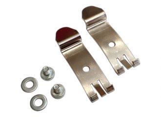
DIN rail clips
- Standard accessory
- Shipped with every RipEX, RipEX2 and RipEX2e unit
- Part No.: HOL-RipEX-DINSET
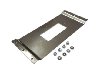
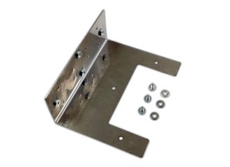
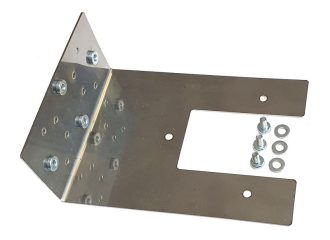
Flat bracket
- For flat surface mounting
- Datasheet, Part No.: HOL-RipEX-FLAT, HOL-RipEX2-FLAT
- Manufactured by RACOM
L bracket
- For vertical mounting
- To DIN rail or directly to a mounting surface
- Datasheet, Part No.: HOL-RipEX-L, HOL-RipEX2-L
- Can not be used when mPCI Extension cellular module is installed in RipEX2
- Manufactured by RACOM
S bracket
- For side mounting
- To DIN rail or directly to a mounting surface
- Datasheet, Part No.: HOL-RipEX2-S
- Manufactured by RACOM
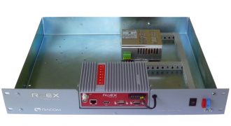
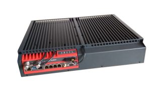
19″ rack chassis
RipEX
- 1.6U (70mm) height
- Ready for assembly with either one (S-single) or two (D-double) RipEX units
- Power options:
- 100 – 230 VAC / 24 VDC, Part No’s.: RipEX-RS-230, RipEX-RD-230
- 48 VDC / 24 VDC, Part No’s.: RipEX-RS-48, RipEX-RD-48
- Dataheet
- Manufactured by RACOM
RipEX2
- 2U height
- Power options
- Built-in duplexer possible
- Chassis also serve as a passive cooler for the unit(s)
- RipEX2-RS
- 1x RipEX2 or RipEX2e
- 1x Power supply
- 1x Built-in duplexer (optional)
- RipEX2-RD
- 2x RipEX2 or RipEX2e
- 2x Power supply
- 2x Built-in duplexer (optional)
- Redundancy
- Redundant antenna system (independent antenna(s) for each unit) and redundant connection of connected technology to “A” and “B” units are required
- Ordering information
- Datasheet
- Manufactured by RACOM
Ingress Protection IP52
- For RipEX2 and RipEX2e only
- RipEX2 and RipEX2e standard Ingress Protection is IP41
- Increase of Protection against Solid objects to IP5x
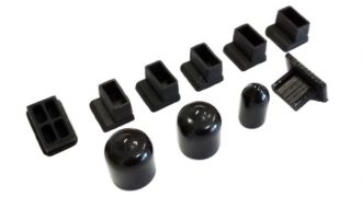
- Dust covers for all unused connectors
- 5x RJ45, 1x USB, 1x SFP, 2x TNC, 1x SMA, (DSUB9 cover is not needed)
- Datasheet, Part No.: SET-RipEX2-IP5x
- Increase of Protection against Water to IPx2
- Unit installed just with connectors facing downward
- Datasheet
- For service and management access to the web interface via USB connector
- Any RipEX provides built-in DHCP server (up to 5 leases)
- Direct easy access from connected device to RipEX management without any reconfiguration
- To access the RipEX always use the fixed IP 10.9.8.7
- To avoid FW compatibility issues it is necessary to order these adapters from RACOM
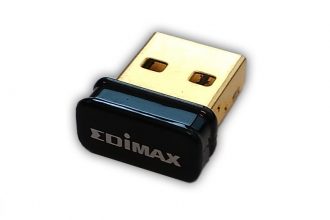
Wi-Fi adapter
- For RipEX only
- Part No.: OTH-USB/WIFI-W1
- Manufactured by Edimax
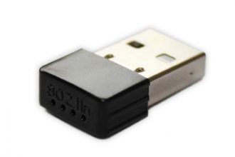
Wi-Fi adapter 2
- For RipEX2 and RipEX2e only
- Datasheet, Part No.: OTH-USB/WIFI-W2
- Manufactured by Ogemray
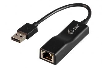
USB/ETH adapter
- For RipEX, RipEX2 and RipEX2e
- FW 1.7.1.0 or higher is required
- Datasheet, Part No.: OTH-USB/ETH-U2
- Manufactured by i-tec
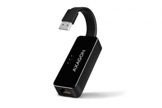
USB/ETH adapter 2
- For RipEX2 and RipEX2e only
- FW 1.4.3.0 or higher is required
- Datasheet, Part No.: OTH-USB/ETH-XR
- Manufactured by Axagon
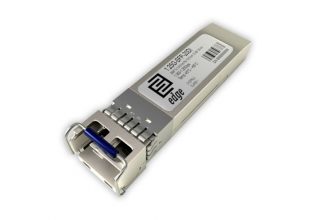
All common types of SFP modules are supported. There are two basic tested modules which RACOM can deliver together with RipEX2 units. If you require anything else, please contact us or your supplier.
SFP module Fibre
- Two fibres
- Single mode
- LC connector
- 20 km
- -45°C to +85°C
- Datasheet, Part No.: SFP-2F-1G-EDGE
- Manufactured by EDGE Technologies
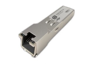
SFP module Ethernet
- Metallic 1 Gb Ethernet
- IEEE 802.3
- RJ45 connector
- -45°C to +85°C
- Datasheet, Part No.: SFP-RJ45-1G-EDGE
- Manufactured by EDGE Technologies
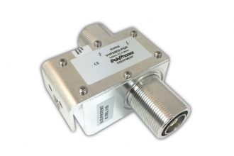
- Coaxial, N(f) / N(f) connectors
- 100 – 512 MHz
- Up to 750 watts
- PLZ0A(B) – LPZ1 zones
- Also suitable for the PLZ0A zone, serving as a lightning conductor
- Low VSWR
- Continuous RF performance after surge (no fuse, automatic reset)
- Flexible bulkhead and bracket mounting capabilities
- IP67
- Datasheet, Part No.: SURGE-COAXIAL
- Manufactured by Polyphaser
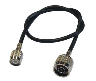
Coaxial Patch cord
- 0.5 m (19.7 in)
- RG58
- TNC(m) / N(m)
- For antenna feedline extension inside of the cabinet, e.g. between RipEX and Coaxial surge protection
- Part No.: CAB-RG58-0.5m
- Manufactured by RACOM
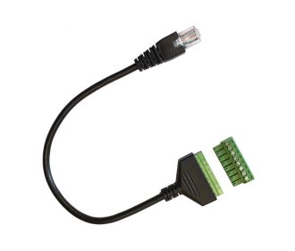
RJ45/Terminals adapter
- For DI/DO connection to RipEX2
- RJ45 to screw terminal block conversion
- 8 pin clamping screw plug (14 – 30 AWG)
- Datasheet, Part No.: OTH-RJ45/SCREW-TERM
- Manufactured by Poyiccot
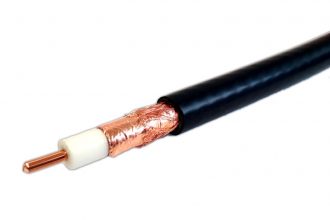
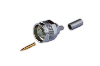
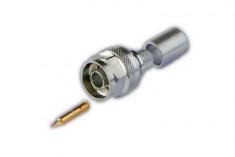
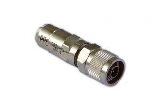
Coaxial connectors
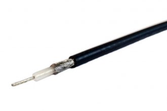
RG58
- N male
- Crimp
- -55 to +155°C
- Datasheet, Part No.: CON-Nm-RG58
- Manufactured by Rosenberger
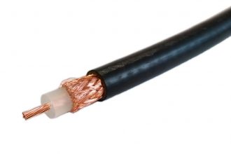
RG213
- N male
- Crimp
- -55 to +155°C
- Datasheet, Part No.: CON-Nm-RG213
- Manufactured by Rosenberger
H1000
- N male
- Screwing
- -40 to +85°C
- Datasheet, Part No.: CON-Nm-H1000
- Manufactured by PPC
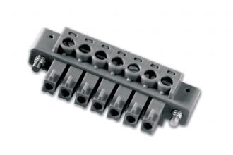
Power connector
- Part of Accessory kit shipped with every unit
- 7 pin clamping screw plug (14 – 30 AWG)
- Datasheet, Part No.: CON-RipEX-PWR
- Manufactured by Tyco
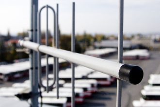
Antennas
It is recommended to source antennas locally, however RACOM is also capable to deliver them. If you would need any help or consultation, don’t hesitate to contact us.
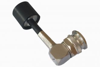
Dummy load antenna
- For laboratory testing
- 50 ohms
- TNC male connector
- Up to 1 W RF output power
- Part No.: ANT-RipEX-DUMMYLOAD
- Manufactured by RACOM
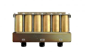
Duplexers
- 140-175 MHz, 300-360 MHz, 400-470 MHz
- Symmetrical, 6 cavities
- Isolation and Inserted loss are dependent on frequency
- Maximum input power 25W
- Impedance 50 ohms
- N female connectors
- Rx and TX frequencies must be specified while ordering
- Datasheet, Part No.: OTH-DUPLEXER
- May be used internally in RipEX2-RS and RipEX2-HS, Part No’s.: RipEX2-HS-HW-DUP
- Manufactured by RCD
Migration solution
These accessories are recommended when Migration solution is implemented.
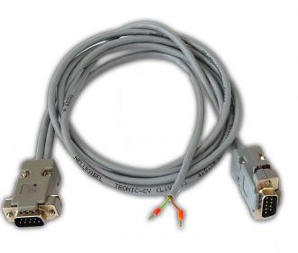
Migration Serial cable
- RS232 cable between RipEX and legacy base station
- 2m (80 in) long
- Crossing cable (null-modem), Rx->Tx, Tx->Rx, GND
- ‘Carrier On’ contact for legacy base station keying (Relay Dry Contact), managed by CTS envelope from RipEX
- DSUB9M – DSUB9M, ‘open wires’ for ‘Carrier On’ contact for legacy base station
- Part No.: OTH-MIG-CAB
- Manufactured by RACOM
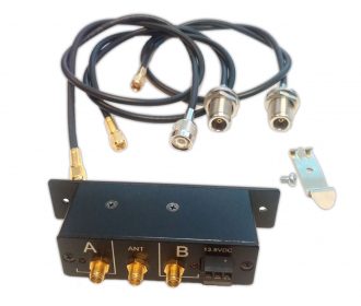
Automatic Antenna Switch
- Automatically manages antenna switching: when one base station transmits, the other one is disconnected from the common antenna
- Attenuation between antenna connectors > 50 dB
- Insertion loss max. 4.5 dB in full frequency range
- RF output power of connected second radio modem up to 25 watts (duty cycle 50%)
- Different models for different frequency bands: 135-174, 300-340, 360-400, 400-470 MHz
- Includes 3 cables RG58 each 50 cm (20 in) long: 1x SMA(f)-TNC(m), 2x SMA(f)-N(f)
- Panel or DIN rail mounting
- Datasheet, Part No.: OTH-MIG-AAS
- Manufactured by RACOM
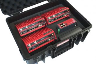
- For 3 pcs of RipEX or RipEX2 or RipEX2e and 1 pc of M!DGE
- Suitable for functional demonstration
- Ready for complete application bench-test
- Rugged and sturdy, Ultra High-Impact ABS Plastic
- Dustproof, airtight, watertight
- Outside dimension: 455 x 365 x 185 mm
- Weight approx. 4 kg (excluding the RipEX’s and M!DGE)
- Part No.: RipEX2-DEMO-CASE
- Manufactured by RACOM
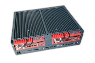
- Redundant hot standby chassis (fully monitored, hot swappable, 1+1 redundant)
- Two booted-up standard RipEX units inside (to be ordered separately)
- Automatic switchover capability on detection of failure
- Suitable for Central sites, Repeaters or Important remote sites where no single point of failure is required
- Details
- Datasheet, Part No‘s.: RipEX-HS, RipEX2-HS
Accessory kit shipped with every unit
RipEX, RipEX2 or RipEX2e
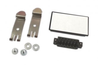
- DIN set – set of two DIN rail clips + two screws, Part No.: HOL-RipEX-DINSET, 1 pc
- Power connector plug, Part No.: CON-RipEX-PWR, 1 pc
- Removable plate with sticker for your notes
RipEX2-HS
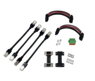
- Interconnecting Ethernet cable (RipEX2 units – controller), 4 pcs
- Interconnecting Power cable (RipEX2 units – controller), 2 pcs
- Interconnecting COM cable + connector screws (RipEX2 units – controller), 2 pcs
- Fuse (250V/2A), 2 pcs
- DC Power and control connector plug (controller), 1 pc
- Mounting kit (also supplied with RipEX2-RS and RipEX2-RD)
- 2× Adjustable rail (adjustable for 19″ Rack depths in range of 380 – 640 mm)
- 2× Locking L-holders
- 10× M6 screws + cage nuts
Calculations
Calculations
Network settings
| Mode | |
| |
| Channel spacing [kHz] | |
| There is an approximately linear relationship between the capacity of the radio channel and the occupied bandwidth. | |
| Average message size | bytes |
| User data size without any headers (IP, TCP, UDP, …). The length of the data transmitted has a major impact on the overall capacity of the network. Long packets have a lower overhead, which is an advantage, but for the Flexible Protocol, too long packets are a disadvantage due to the increased possibility of collisions on the radio channel. | |
| Number of sites | |
| Total number of stations communicating between. A higher number of stations increases the probability of collision for networks in Flexible mode. | |
| Number of stations behind repeater | |
| The number of stations out of the total that are behind the repeater. The BDP protocol allows a maximum of two radio hops between the base and the remote radio. | |
| Average hops per path to remote | |
| Average hop count to the remote sites. E.g. 9 remote stations directly connected to the center (one radio hop) and one remote station over one repeater (two radio hops) results in 1.1. The Flexible protocol has an unlimited number of radio hops between centrum and remote radio. | |
Results
The results obtained from this calculator should be considered approximate and are primarily intended to provide a rough overview of expected network performance. Actual network throughput can vary significantly depending on a number of factors. More information
One of the most important factors is the compressibility of the data being transmitted, as less compressible data can reduce transmission efficiency. The real frame reception time also plays a critical role in accessing the radio channel.
In addition, the network topology - specifically the arrangement and interconnection of individual devices - can have a significant impact on performance, as can various environmental factors such as interference from other radio signals, terrain obstacles or weather conditions.
All of these parameters can cause the actual throughput to be higher or lower than the calculator results.
For these reasons, only the following key parameters are included in the calculation. Setting the radio protocol and transmission parameters in RipEX radio routers is more complex than the parameters listed in this calculator.
Download
| Product overview | ripex-product-overview.pdf | 2 118 kB | 01.08.2019 |
| Datasheet RipEX - A4 - ver.4.4 - English | ripex-dsA4-en.pdf | 2 073 kB | 23.10.2025 |
| Datasheet RipEX - A4 - ver.4.4 - Česky | ripex-dsA4-cz.pdf | 1 899 kB | 23.10.2025 |
| Datasheet RipEX - A4 - ver.4.4 - En español | ripex-dsA4-es.pdf | 1 867 kB | 23.10.2025 |
| Datasheet RipEX - A4 - ver.4.4 - Francais | ripex-dsA4-fr.pdf | 1 922 kB | 24.10.2025 |
| Datasheet RipEX - A4 - ver.4.4 - Em português | ripex-dsA4-po.pdf | 1 952 kB | 24.10.2025 |
| Брошюра RipEX - A4 - ver.4.4 - По-русски | ripex-dsA4-ru.pdf | 1 976 kB | 24.10.2025 |
| Datasheet RipEX Hot Standby | RipEX-HS-A4-en.pdf | 427 kB | 01.09.2023 |
| RipEX – Radio modem & Router - DEMO handbook | ripex-case-man-en.pdf | 3 640 kB | 14.10.2021 |
| User manual RipEX2, RipEX2e | ripex2-man-en.pdf | 17 901 kB | 13.01.2026 |
| User manual RipEX2-HS | ripex2-hs-m-en.pdf | 13 549 kB | 20.11.2025 |
| User manual RipEX | ripex-man-en.pdf | 12 044 kB | 22.07.2024 |
| Base Driven protocol | ripex-base-driven-protocol-is.pdf | 1 202 kB | 28.01.2025 |
| Data speed | ripex-data-speed-is.pdf | 1 796 kB | 07.01.2020 |
| Flexible protocol | ripex-flexible-protocol-is.pdf | 508 kB | 07.01.2020 |
| Hybrid networks | ripex-hybrid-networks-is.pdf | 1 924 kB | 07.01.2020 |
| Migration solution | ripex-migration-solution-is.pdf | 458 kB | 10.04.2025 |
| Power distribution - CFE, Mexico | ripex-cs-cfe-en.pdf | 2 902 kB | 25.02.2016 |
| Water management - WSC, Malta | ripex-cs-wsc-en.pdf | 1 281 kB | 24.09.2015 |
| WSC Malta whitepaper | wsc-psaila-wp-en.pdf | 443 kB | 24.09.2015 |
| RipEX Firmware package 1.9.7.0 | ra1-RACOM-1.9.7.0.cpio | 11 873 kB | 23.07.2021 |
| Firmware Release notes | ripex-fw-rn-en.pdf | 368 kB | 11.05.2022 |
| MIB table | ripex-mib.zip | 26 kB | 16.09.2019 |
| Zabbix ver. 6 templates | ripex-zabbix-v6.0.zip | 4 480 kB | 23.06.2022 |
| Firmware Release notes | ripex2-fw-rn-en.pdf | 683 kB | 07.11.2025 |
| Firmware | ripex2-fw-2.2.9.0.fwp | 42 139 kB | 07.11.2025 |
| Firmware SHA-256 checksum | ripex2-fw-2.2.9.0.fwp.sha256 | 0 kB | 07.11.2025 |
| Firmware patch | ripex2-fw-2.2.9.0-patch-2.2.4.0.fwp | 8 514 kB | 07.11.2025 |
| Firmware patch SHA-256 checksum | ripex2-fw-2.2.9.0-patch-2.2.4.0.fwp.sha256 | 0 kB | 07.11.2025 |
| Firmware patch | ripex2-fw-2.2.9.0-patch-2.2.6.0.fwp | 184 kB | 07.11.2025 |
| Firmware patch SHA-256 checksum | ripex2-fw-2.2.9.0-patch-2.2.6.0.fwp.sha256 | 0 kB | 07.11.2025 |
| MIB table 2.2.9.0 | ra2-mib-2.2.9.0.zip | 26 kB | 14.10.2025 |
| Zabbix ver. 7 templates 2.2.6.0 | ripex2-zabbix-7.0-2.2.6.0.zip | 5 017 kB | 14.10.2025 |
| YANG data model | ripex2-yang-2.2.9.0.zip | 230 kB | 14.10.2025 |
| USB adapters | |||
| Adapter USB/ETH (RipEX2, M!DGE2, RAy3), Axagon | OTH-USB_ETH-XR.pdf | 110 kB | 18.08.2020 |
| Adapter USB/ETH (RipEX, RipEX2, M!DGE2, RAy2, RAy3), i-tec | OTH-USB_ETH-U2.pdf | 398 kB | 16.04.2021 |
| Adapter USB/Wi-Fi (RipEX2, RAy2, RAy3), Ogemray | OTH-USB_WIFI-W2.pdf | 219 kB | 10.12.2018 |
| SFP modules | |||
| SFP module, 1 Gb Ethernet, RJ45, EDGE | SFP-RJ45-1G-EDGE.pdf | 291 kB | 16.01.2021 |
| SFP module, 2 fibres, SM, LC, 20 km, EDGE | SFP-2F-1G-EDGE.pdf | 477 kB | 08.11.2019 |
| Power supplies | |||
| Power supply 90-264VAC/12VDC/75W, DIN, MeanWell | PWS-AC,DC_12VDC_75W2.pdf | 654 kB | 23.08.2021 |
| Power supply with back-up 90-260VAC/13.8VDC/97W | PWS-AC,DC_13.8VDC_97W.pdf | 1 113 kB | 05.08.2020 |
| Mounting | |||
| 19" rack chassis for RipEX | RipEX-Rx.pdf | 721 kB | 11.12.2019 |
| 19" rack chassis for RipEX2 | RipEX2-Rx.pdf | 2 011 kB | 03.02.2021 |
| Bracket for flat surface mounting | HOL-RipEX1-2-FLAT.pdf | 971 kB | 10.12.2019 |
| Bracket for side mounting | HOL-RipEX2-S.pdf | 834 kB | 06.02.2023 |
| Bracket for vertical mounting | HOL-RipEX1-2-L.pdf | 1 643 kB | 03.02.2021 |
| Set of connector dust covers for RipEX2 | SET-RipEX2-IP5x.pdf | 1 837 kB | 03.02.2021 |
| Surge protection | |||
| Surge protection coaxial, N(f)/N(f), PLZ0A(B)-LPZ1, Polyphaser | SURGE-COAXIAL.pdf | 414 kB | 12.05.2017 |
| Cables & Connectors | |||
| Adapter RJ45/Screw Terminal Blocks (RipEX2, M!DGE3), Poyiccot | RJ45-Terminals-adapter.pdf | 244 kB | 10.04.2024 |
| Coaxial cable H1000, Belden | CAB-H1000.pdf | 135 kB | 19.08.2025 |
| Coaxial cable RG213, atten. 13.8 dB/100m/400MHz, Draka | CAB-RG213.pdf | 49 kB | 14.03.2019 |
| Coaxial cable RG58, atten. 29.7dB/100m/400MHz, Draka | CAB-RG58.pdf | 78 kB | 14.03.2019 |
| Connector N male, for H1000, screwing, PPC | CON-Nm-H1000.pdf | 134 kB | 14.03.2019 |
| Connector N male, for RG213, crimp, Rosenberger | CON-Nm-RG213.pdf | 65 kB | 14.03.2019 |
| Connector N male, for RG58, crimp, Rosenberger | CON-Nm-RG58.pdf | 84 kB | 14.03.2019 |
| Connector, RipEX, Power plug with terminals | CON-RipEX-PWR.pdf | 238 kB | 14.03.2019 |
| Migration solution | |||
| Automatic Antenna Switch, cables included | OTH-MIG-AAS.pdf | 205 kB | 03.10.2025 |
| Duplexers | |||
| Duplexer, 6 cavities, RCD | OTH-DUPLEXER.pdf | 219 kB | 13.09.2020 |
| DEMO case | |||
| User manual - Demo case | ripex-case-man-en.pdf | 3 640 kB | 10.04.2019 |
Mesh RF backbone
Dynamic routing (BABEL)
Solar powered nodes
LTE failover
Power and Water Distribution
Base driven protocol
DNP3
Ongoing migration
DPSK to 256 QAM
25 kHz bandwidth
Underground
Leaky Feeder
256QAM
Point to Multipoint
