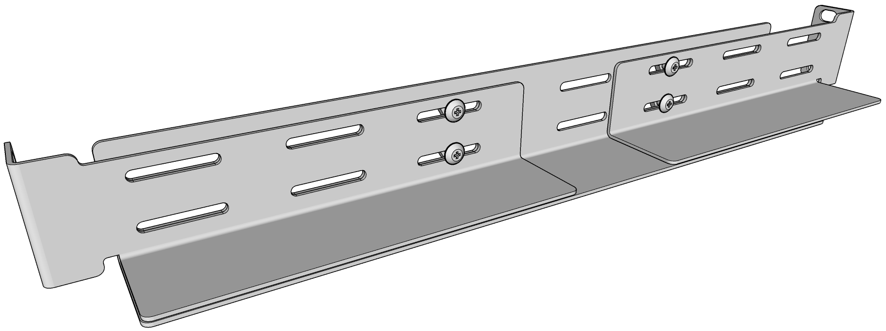
RipEX2-HS is delivered by default with Mounting kit, which contents:
2× Adjustable rail (adjustable for 19″ Rack depths in range of 380-640mm)
2× Locking L-holders
10× M6 screws + cage nuts
| Note | |
|---|---|
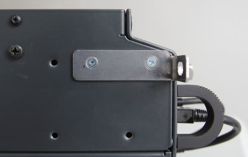
Pull-out holders (placed on both front sides of the chassis) servers only for pulling the RipEX2-HS out of the shelf, not for carying. |
Power supply according to the HW variant of RipEX2-HS see
https://www.racom.eu/eng/products/ripex-hot-standby.html#features
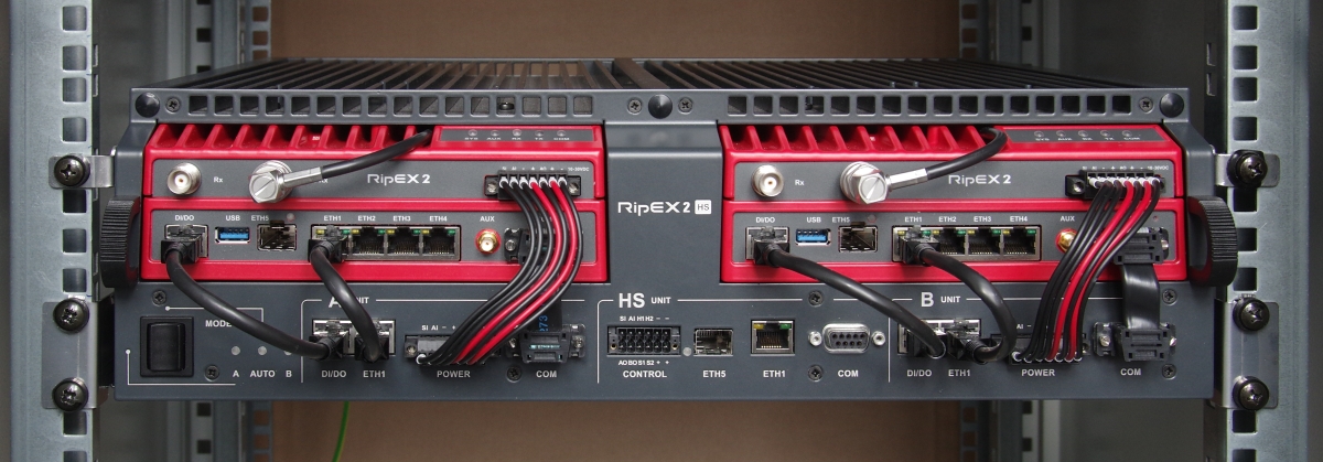
Since there are two independent power supplies, one for each RipEX2 unit, it is recommended to connect each power supply to a separate power phase with individual circuit breakers. When one phase would be off, RipEX2-HS will still be On.
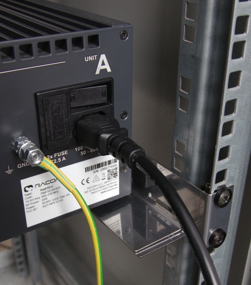
There are individual power connectors for each power supply. See Section 2.3, “Rear panel”.
There are also two independent power supplies with 36 to 60 V DC input voltage, one for each RipEX2 unit; input conductors are isolated from the rest of the RipEX2-HS and thus allows positive or negative grounding. The electric strength is 4 kV AC / 1 min.
| Note | |
|---|---|
When positive grounding is used, neither device connected via RS232, USB, ETH can have negative grounding! |
There are individual power connectors for each power supply. See Section 2.3, “Rear panel”
There is not any internal power supply in this option, powering is the same as for standard RipEX2.
The supply must be capable of providing the required input for the projected RF output. The power supply must be sufficiently stable so that voltage does not drop when switching from receive to transmit, which takes less than 1.5 ms. To avoid radio channel interference, power supply must meet all relevant EMC standards. Never install a power supply close to the antenna. Maximal supply cable length is 3 m, and recommended wire cross section 1.0 mm2.
There are also two independent power supplies with 18 to 30 V DC input voltage, one for each RipEX2 unit; input conductors are isolated from the rest of the RipEX-HS and thus allows positive or negative grounding. The electric strength is 4 kV AC / 1 min.
When positive grounding is used, neither device connected via RS232, USB, ETH can have negative grounding! There are individual power connectors for each power supply. See section 3.3, “Rear panel”
The grounding screw on the rear panel has to be properly connected to the grounding point of the rack. The minimal required copper conductor cross-section is 4 mm2.
For antenna installation refer to RipEX User manual.
RipEX2-RS is a 19″ rack-mount chassis designed for installing a RipEX2 radio unit. The chassis also provides additional passive cooling and can accommodate optional accessories, such as a power supply or a duplexer.
Full Duplex Operation
A duplexer is required when the RipEX2 operates in full-duplex mode. Full-duplex operation is supported only in Point-to-Point configurations consisting of two RipEX2 units, each mounted in its RipEX2-RS chassis.
Each link uses a pair of operating frequencies:
Unit “Low” transmits on the lower frequency and receives on the higher frequency.
Unit “High” transmits on the higher frequency and receives on the lower frequency.

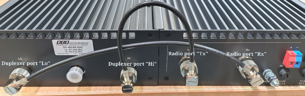
Cabling – Low Unit
The “Low” radio unit must be connected as follows:
Duplexer port “Lo” → Radio port “Tx”
Duplexer port “Hi” → Radio port “Rx”

Cabling – High Unit
The “High” radio unit must be connected as follows:
Duplexer port “Lo” → Radio port “Rx”
Duplexer port “Hi” → Radio port “Tx”
Interconnection Notes
If the RipEX2-RS chassis is supplied with the duplexer pre-installed, the interconnection cables between the RipEX2 antenna ports and the duplexer ports are shipped dismounted for transport. They must be installed before mounting the chassis.
It is essential to ensure that the hardware cabling matches the software configuration of each RipEX2 unit (transmit and receive frequencies). Incorrect cabling or configuration will prevent proper operation.