There are two standard RipEX2 units with identical configurations inside RipEX2-HS. Both units are booted, however only one is active. Some interfaces (COM, ETH1 and Radio) of the non-active unit are disconnected.
| Note | |
|---|---|
Even if Rx on inactive RipEX2 unit LED panel is blinking when the active unit is transmitting, these packets are not received. I.e. they don’t take part in Statistic, Neighbours or Graphs. |
When the active unit HW alarm output changes to “On” (e.g. when a controlled value exceeds the respective threshold), the controller automatically switches interfaces (COM, ETH1, ANT–if applicable) to the second unit and it takes over all functions. Since both units are using the same MAC addresses (MAC cloning), there is a minimal drop-out while switching, approx 5 s.
When RipEX2 units inside RipEX2-HS are in Bridge mode, the first switch-over takes approx. 30 s. It is because hot standby RipEX2 ARP table is clear and has to be filled with first packets (forward delay). The next switch-over takes approx 5 s. When Operating mode is Router, even the first switch-over takes approx 5 s. When ARP proxy in Router mode is used, switch-over time(s) is equal to that of the Bridge mode.
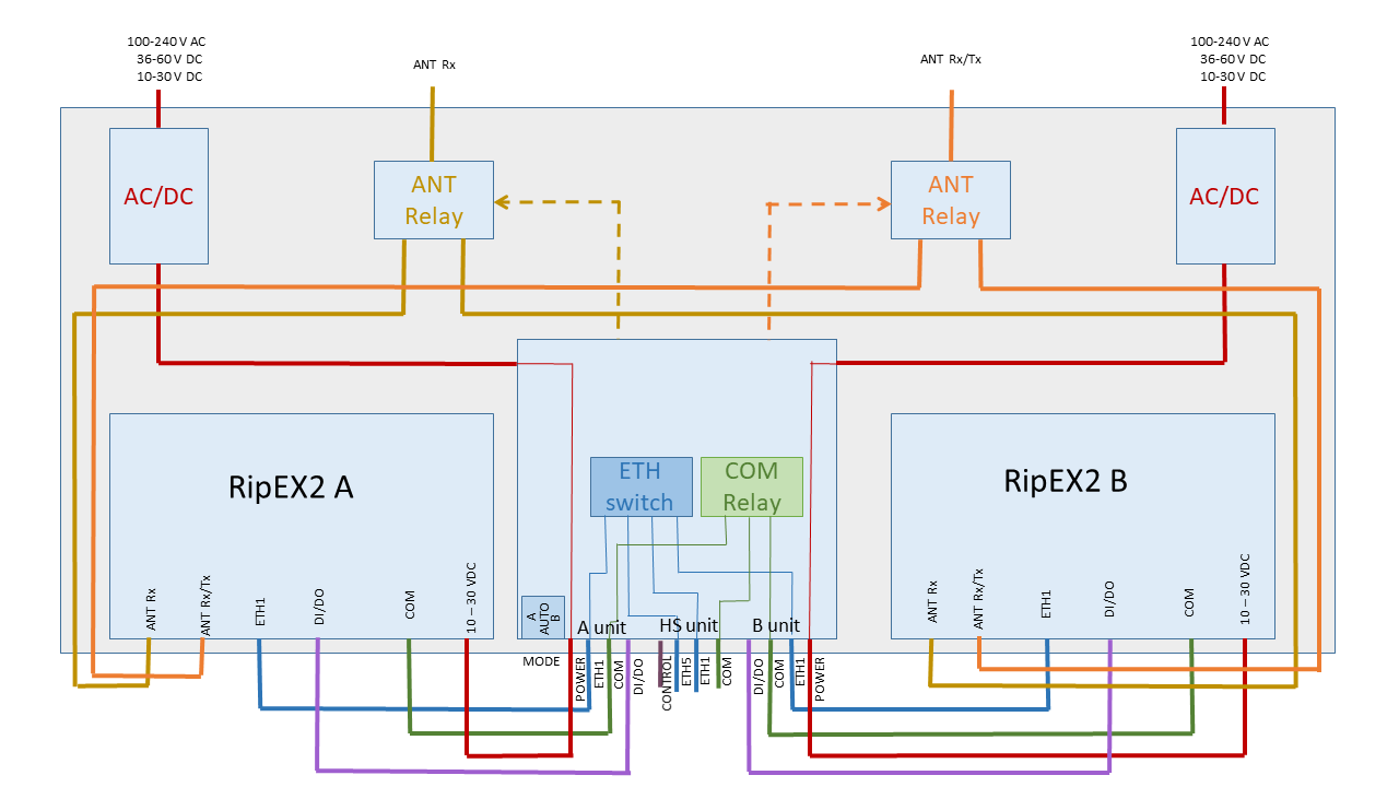
Auto – primary active is RipEX2 “A”, when it fails, controller automatically switches-over to RipEX2 “B”. When both units are with alarms, “A” unit remains active.
A – only RipEX2 “A” is active and controller will never switch to RipEX2 “B”
B – only RipEX2 “B” is active and controller will never switch to RipEX2 “A”
A and B modes are supposed to be used only for the maintenance/testing and not for normal service.
In order to achieve maximum reliability, the controller is software free. Switching-over is based only on HW alarm outputs of RipEX2 units and the HW signals from their power supplies.
The HW alarm of active RipEX2 or its power supply will cause the immediate and unconditional switch-over to hot standby RipEX2. If there are any packets waiting in queues of RipEX2 which becomes inactive, these packets are discarded after switch-over.
Power supply of respective unit is “Off” when the input voltage from the respective
power supply to the controller is out of voltage working range.
Some borderline examples for Auto mode (Primary unit is always “A”. The second unit is standby):
Power alarm of Primary unit is “On”
– Standby unit becomes activePrimary unit alarm is “On” and Power alarm of Standby is “On” or Standby unit alarm is “On”
– Nothing will be done. Primary unit remains activePrimary unit alarm is “On”, it was switched to Standby unit, Primary unit alarm disappeared
– it will be switched back to Primary unit immediately (the protective timeout of 30 s will be held for shorter HW alarm output changes)
In order to achieve maximum reliability, the controller is software free. Switch-over is based only on HW alarm outputs of RipEX2 units and their power supplies.
Switch-over is based on HW alarm outputs of RipEX2 units, their power supplies and detector of radio Tx and antenna degradation.