The settings of individual RipEX2 units is available in RipEX2 User manual chapter 7 Settings. Only special settings for controller version of the RipEX2-HS is mentioned bellow.
Following settings is supported by the controller version of the RipEX2-HS, where the controller manages the active and passive/standby RipEX2-HS units and their accessing to the shared channels (e.g. radio).
The HW switch (mode selector) has to be set to AUTO position for switching between units, otherwise the selected unit remains active even if an error occurs on the selected one.
AUTO regime allows switching to the standby unit when an error status occur in active unit – if both units are without alarms, the A unit will be active.
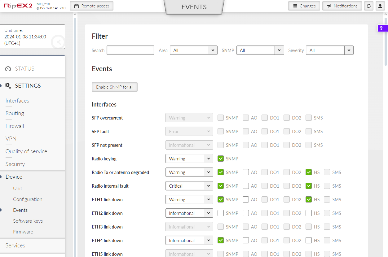
For detailed settings of unit switching (and its conditions of switching) see sections Events and Antenna detection in RipEX2 User manual and section “Switching over” Ripex2-HS.
| Important | |
|---|---|
The communication between individual RipEX2-HS units and HS controller use DI/DO interfaces, so other use of these interfaces is not possible. |
| Note | |
|---|---|
HW option RipEX2e (product variant ‘H’ and ‘J’) cannot be used in Hot standby configuration. |
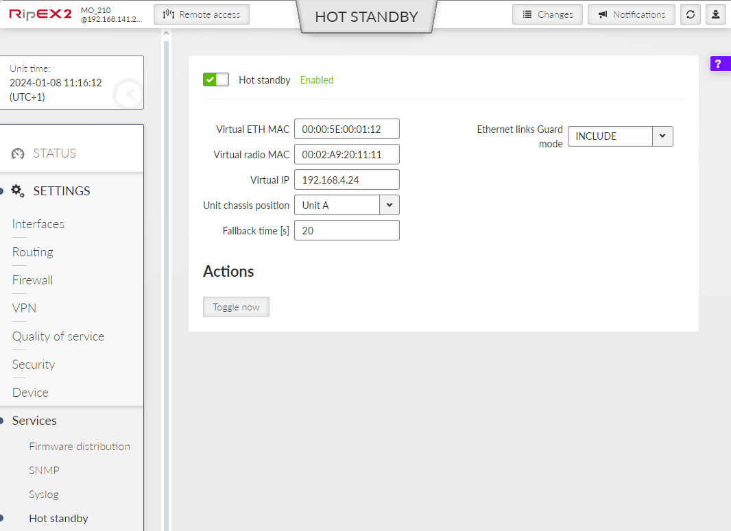
Hot standby mode enabled
List box {On; Off }, default = “Off”
Switches Hot Standby functionality.Virtual ETH MAC
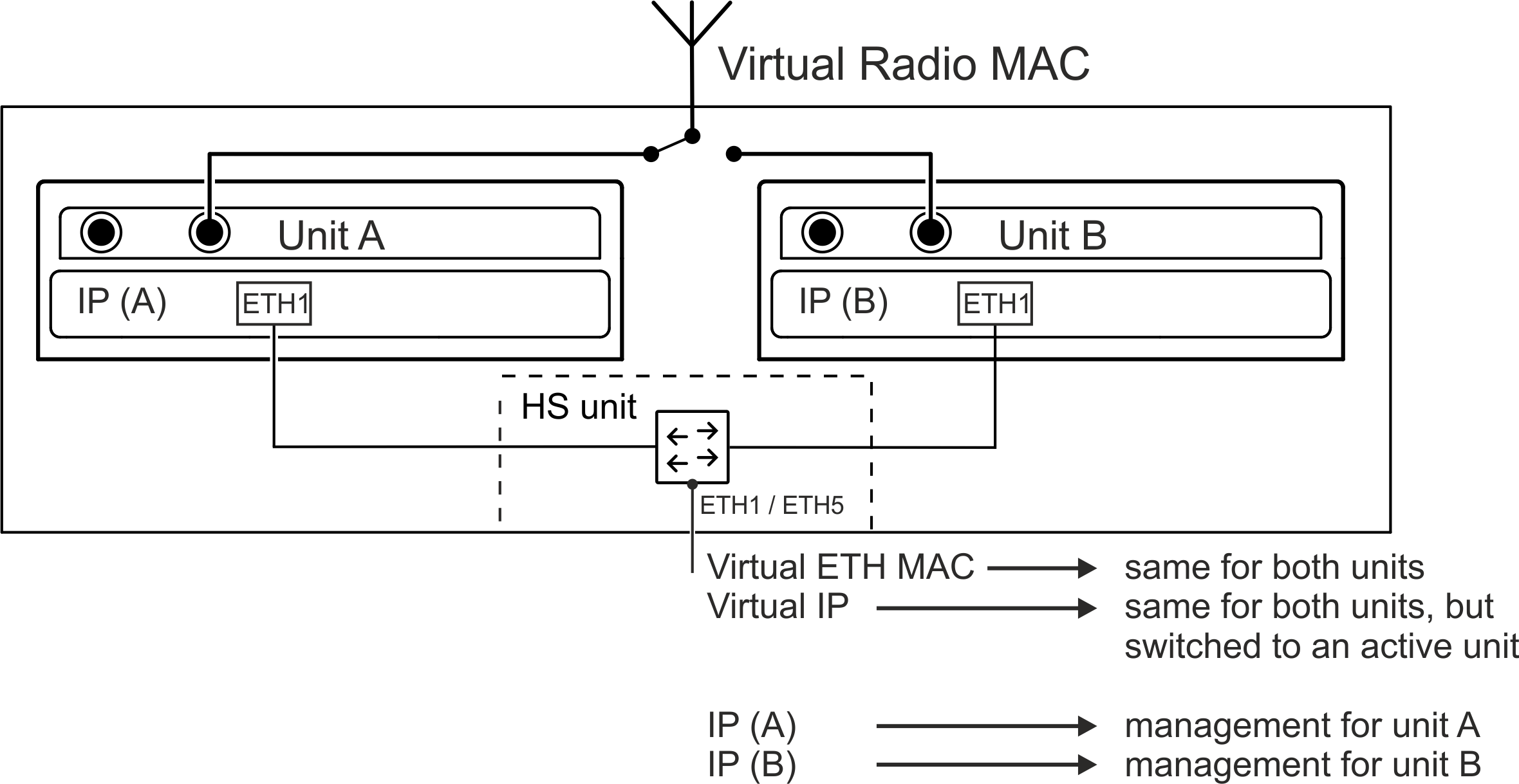
MAC address of shared LAN interface. It should be same for both individual RipEX2-HS units. This MAC address has to differ from other MAC addresses used in unit. It is possible to use e.g. VRRP type of addresses: 00:00:5E:00:01:XX.Virtual Radio MAC
While in HotStandby mode, it is necessary to set identical radio MAC address (HotStdby_RadioMac) in both stations, because protocol link address is derived from the address.
Virtual Radio MAC address has to differ from Virtual MAC address and all other addresses in the unit.
This parameter is used only, if the unit is running on Flexible protocol.
To prevent a collision with broadcast addresses (in case of Flexible protocol usage), the address must not be ended with :FF:FF:FF.
Virtual IP
This address has to fit into range of addresses used for the relevant network interface (e.g. ETH 1) and will be used as shared IP address for LAN interface. Typically used for connection of attached technology.![[Note]](/images/radost/images/icons/note.png)
Note The radio address used according to setting in SETTINGS > Interfaces > Radio > IP / Mask (and check “Range for virtual address” option) – the same address has to be set in both radio modems.
Unit chassis position
List box {Unit A; Unit B}, default = “Unit B”
Position of the unit in HS chassis, set Unit A for unit in A position and vice versa.Fallback time
Time in seconds. The time delay to stay on the standby unit, after all alarms are solved.Ethernet links Guard mode
List box {INCLUDE; EXCLUDE}, default = “INCLUDE”
Defines the behavior of guarding of ETH interfaces. “INCLUDE” requires all guarded lines in UP status – if one of these guarded lines is not in UP state, alarm occurs and the switching to the standby unit is executed. “EXCLUDE” requires at least one guarded line in UP status.Toggle now
This button allows to switch from unit Active status to the non-active.It will not be possible if:
The second unit is in alarm status.
The HW MODE selector is not set to AUTO.
The unit is in not-active status.
It is necessary to set LAN interface used for HS functionality.
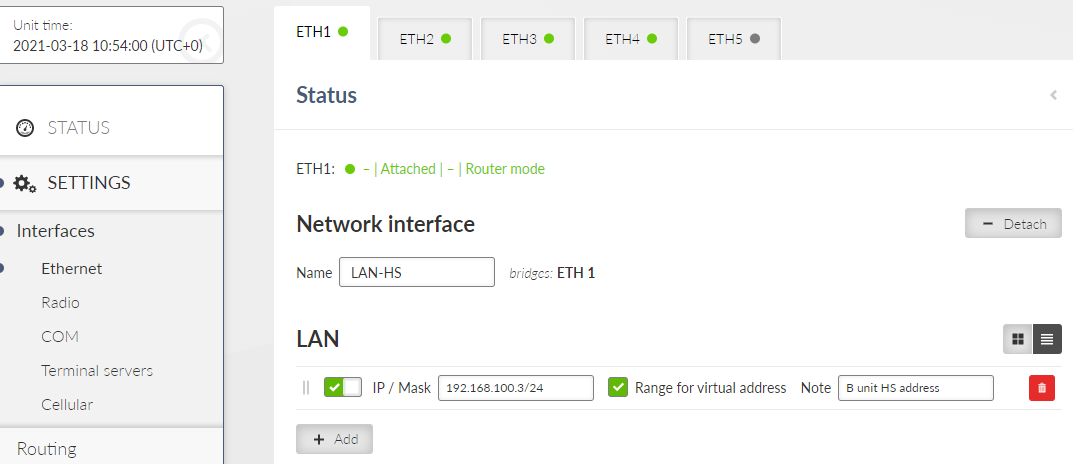
The Range for virtual address parameter is in this menu available only when HS functionality in the menu SETTINGS > Services > Hot standby is enabled (see above).
The parameter Range for virtual address has to be set to On for the LAN address interconnected with shared ETH interface (Range for virtual address set to On).
| Note | |
|---|---|
Interconnected ETH interface IP addresses of both ETH addresses must be different as well as addresses of A and B units, yet in the same range as the virtual shared address (= together three different addresses in the same range). |