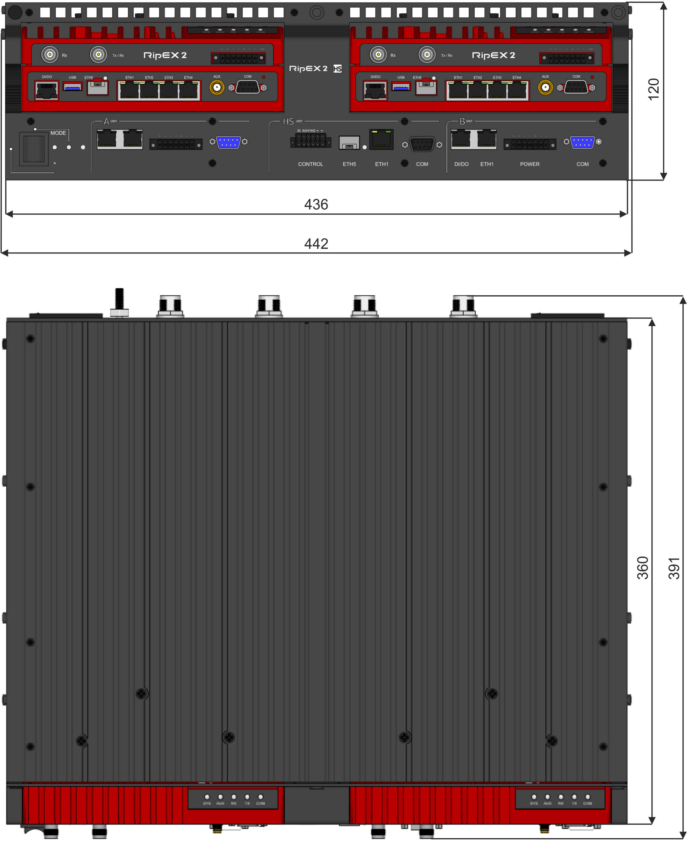
19″ rack 3U, H × W × D: 120 × 442 × 360 mm (4.72 × 17.40 × 14.17 inch.)
19″ rack 3U, H × W × D: 87 × 442 × 360 mm (3.42 × 17.40 × 14.17 inch.)
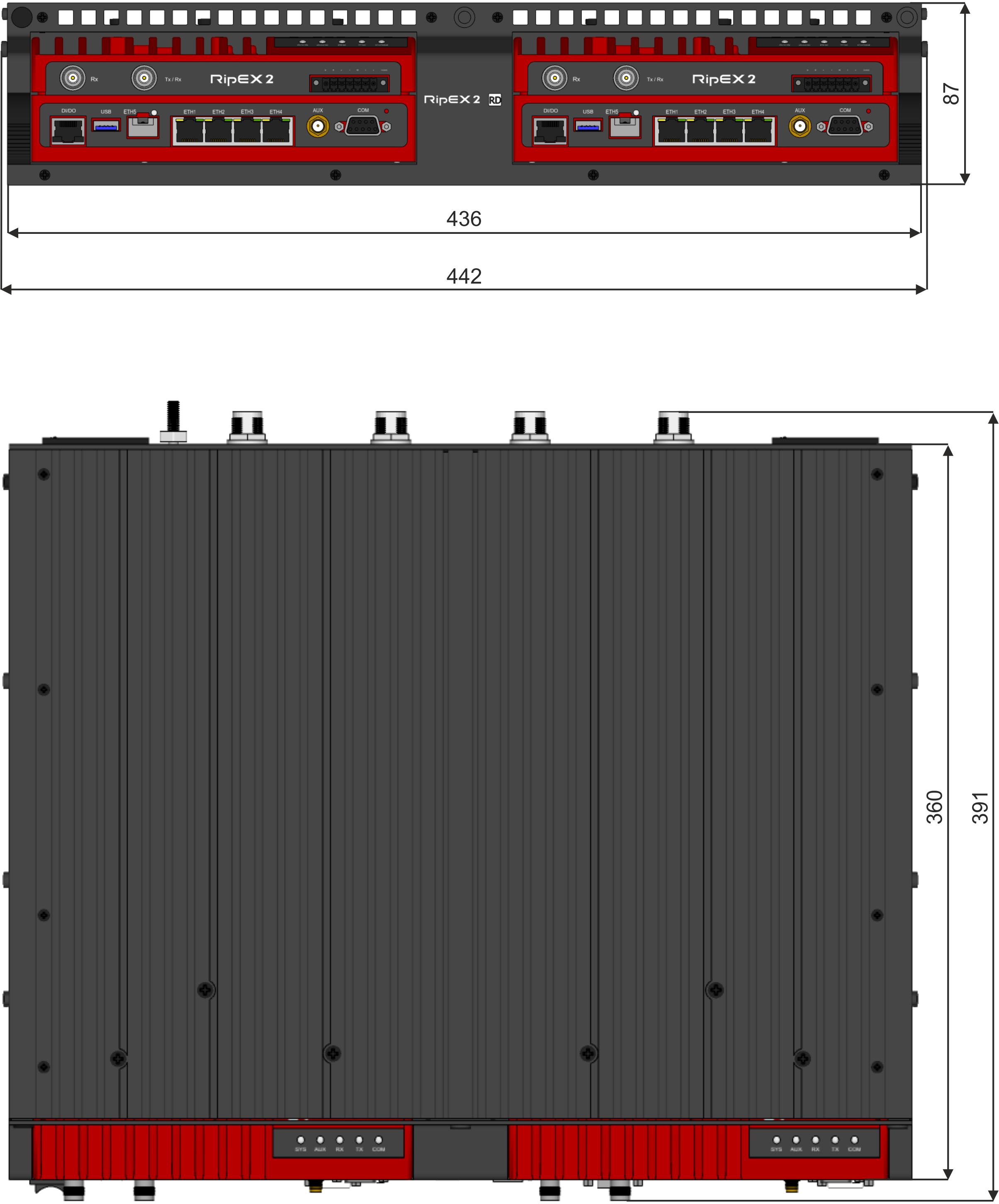
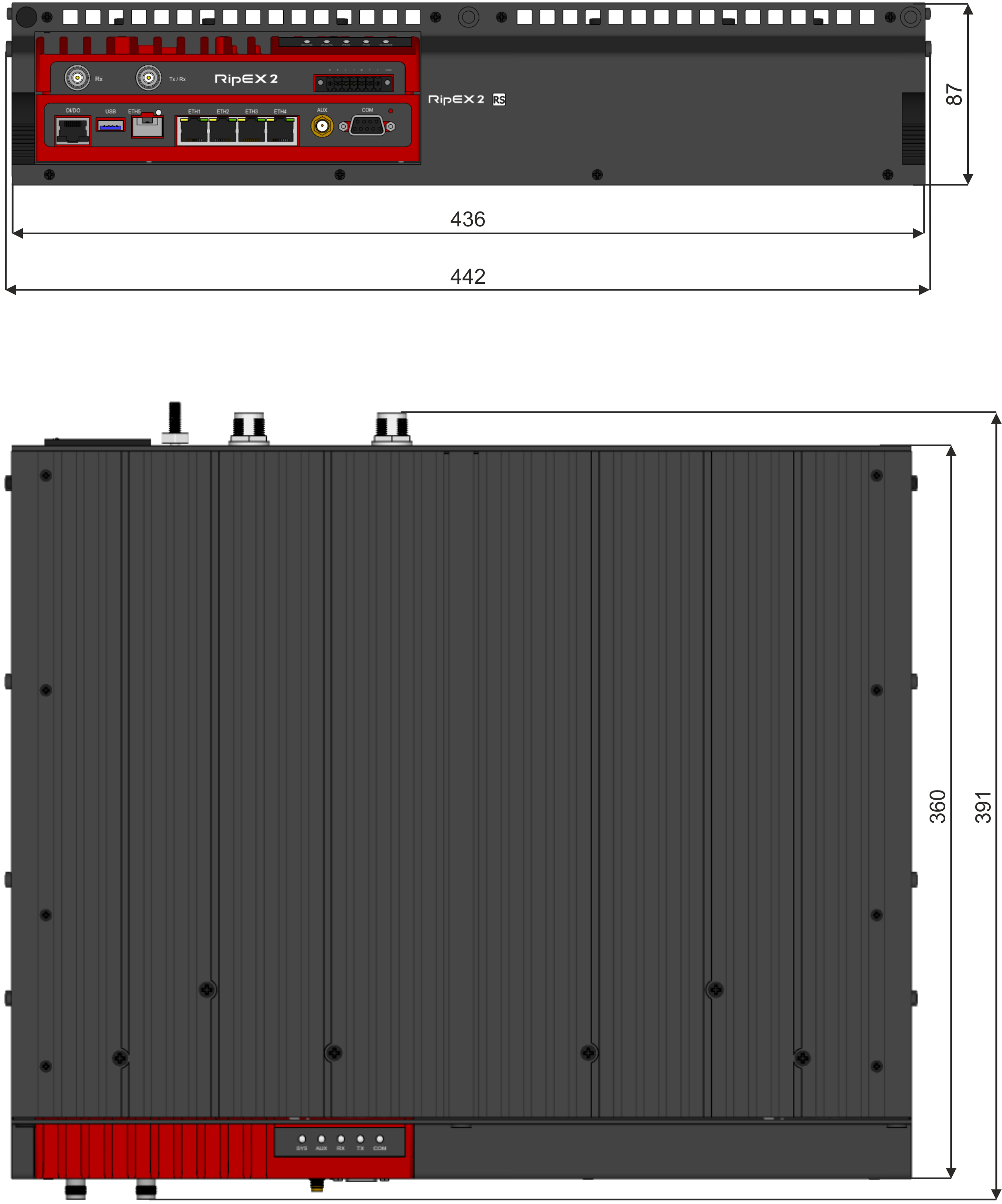
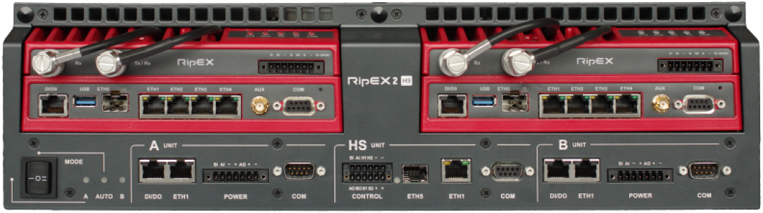
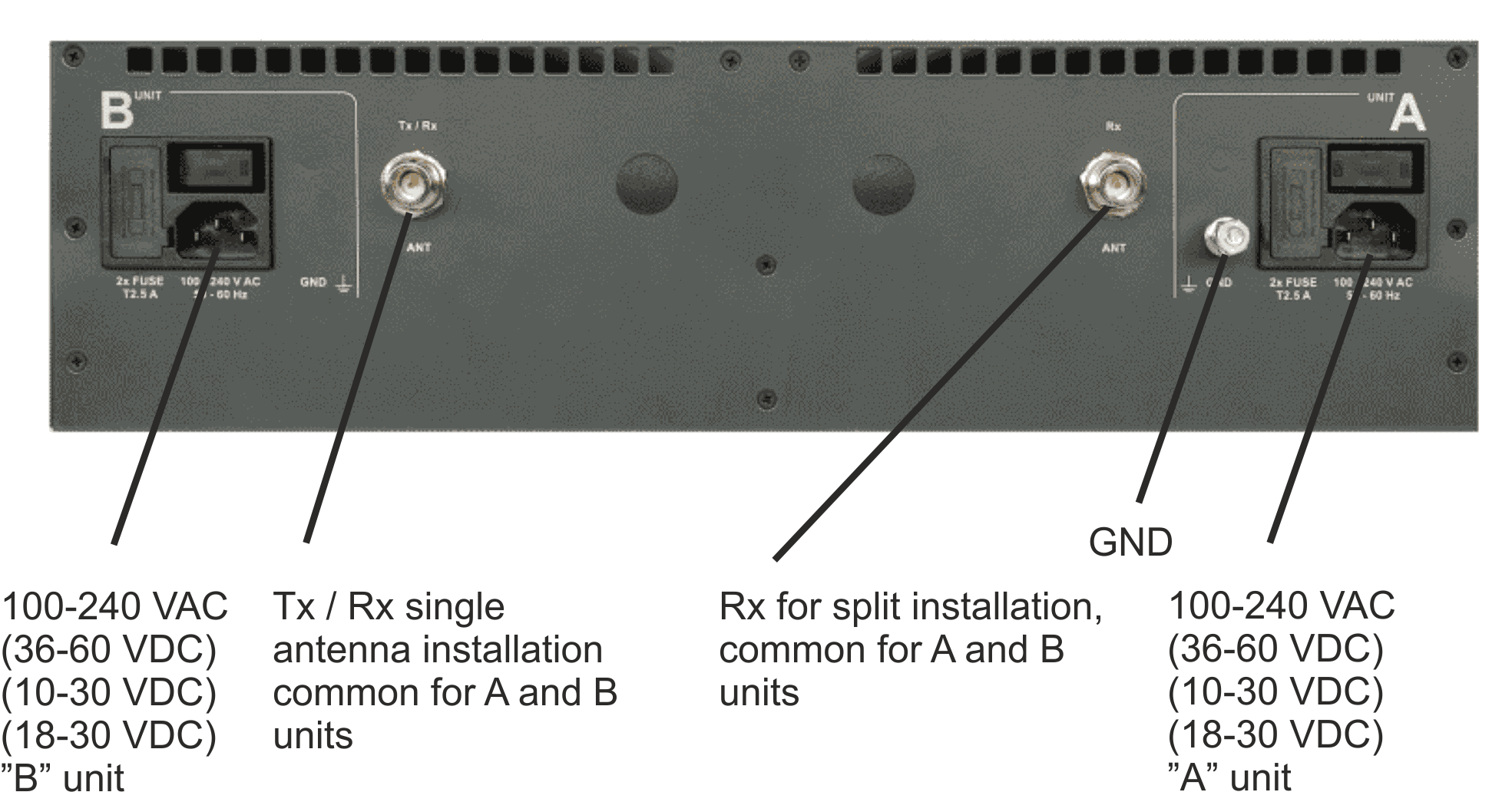
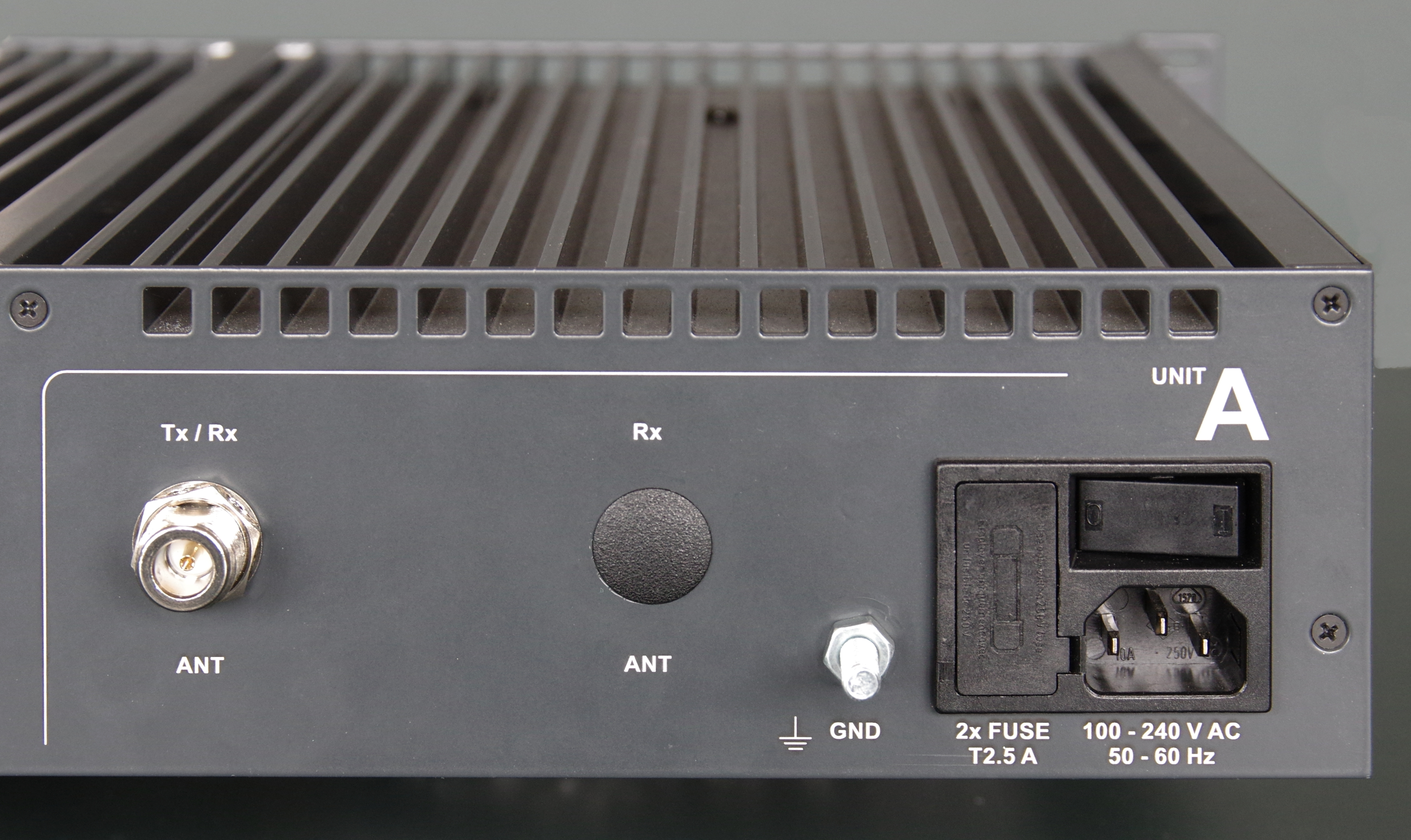
All connectors for RipEX2 units are described in RipEX2 User manual (Chap. 1.2)
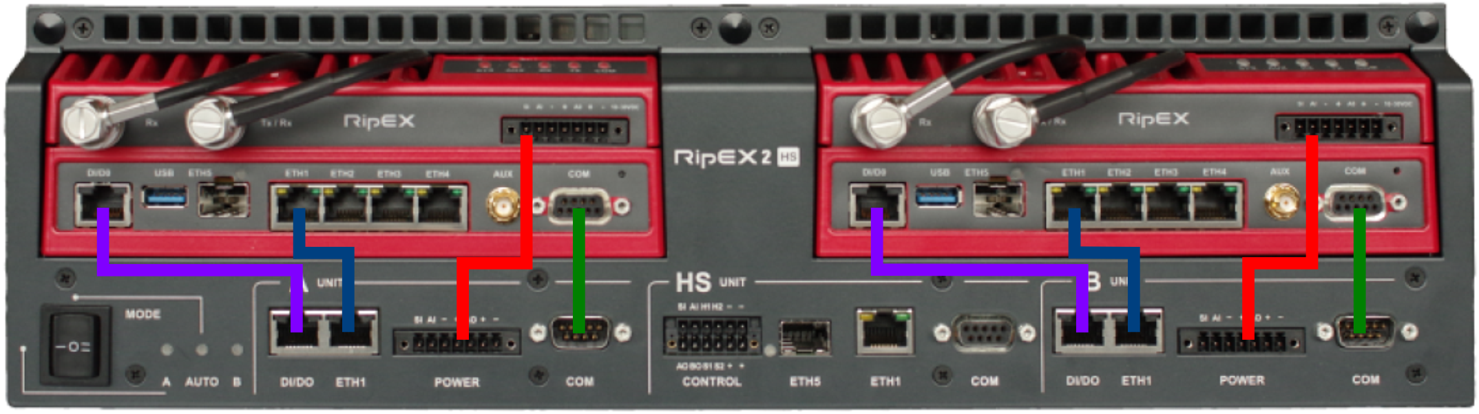
Connectors of the RipEX2-HS are splitted to three sections: HS unit, “A” unit and “B” unit.
Connectors of this sections serves as connection with external equipment.
Description of each connector is the same as with RipEX2 unit and you can find it in RipEX2 manual.
ETH1 and ETH5 (SFP) are connected to an internal switch, for connection of both ETH to the individual RipEX2, units the ETH1 connector in A unit and B unit section shall be used.
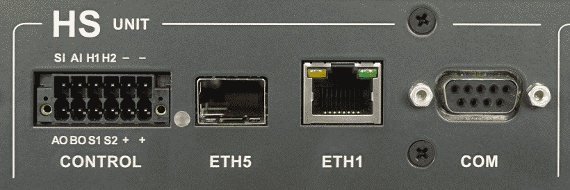
12 pin connector (Type of plug Phoenix Contact 1790331)
| Pin description | |
|---|---|
| SI Sleep input | This input is connected to the SI pin on power connector of the active RipEX2 unit |
| AI Alarm input | This input is connected to the AI pin on power connector of the active RipEX2 unit |
| H1 | Allows HW driven switching between active units in AUTO mode |
| H2 | Allows HW driven switching between active units in AUTO mode |
| AO | Alarm output of the “A” unit RipEX2 |
| BO | Alarm output of the “B” unit RipEX2 |
| S1 | Alarm status output – indication of an alarm of HS controller |
| S2 | Alarm status output – indication of an alarm of “A” unit or/and “B” unit |

Connectors of this section has to be interconnected with respective connectors of appropriate RipEX2 unit.
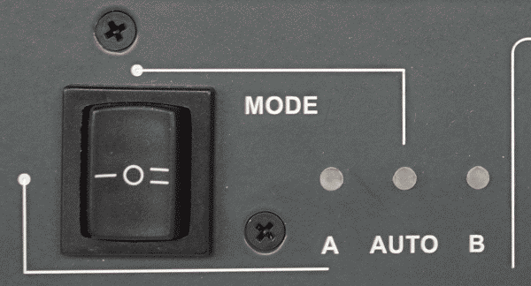
Tab. 2.1: LED panel description
| Symbol | Description | |
|---|---|---|
| 1 | AUTO |
Dark mode AUTO is not active Green solid – ready, both RipEX2 units powered and no alarm known red solid – alarm status, when only this LED is red indicates alarm of the controller, otherwise together with unit in alarm status dark – RipEX2 “A” is not active |
| 2 | A |
Green solid – Unit “A” active – selected as active by switch green blinking – AUTO mode ready to serve Red solid – unit in alarm status Red blinking – power supply alarm (together with red solid AUTO LED) |
| 3 | B |
Green solid – active – selected as active by switch Green blinking – AUTO mode ready to serve Red solid – unit in alarm status Red blinking – power supply alarm (together with red solid AUTO LED) |
Tab. 2.2: MODE selector
| MODE | Description |
|---|---|
| A |
RipEX2 unit “A” hard selected – it remains active even in case of alarm on unit “A” |
| AUTO |
AUTO mode – A unit active till an alarm status on “A” unit occurs, which causes switching to unit “B”. |
| B |
RipEX2 unit “B” hard selected – it remains active even in case of alarm on unit “B” |
For more details see Chapter 4, RipEX2-HS in detail.
| Note | |
|---|---|
When testing the changeover, please wait at least 30 seconds between individual tests. |
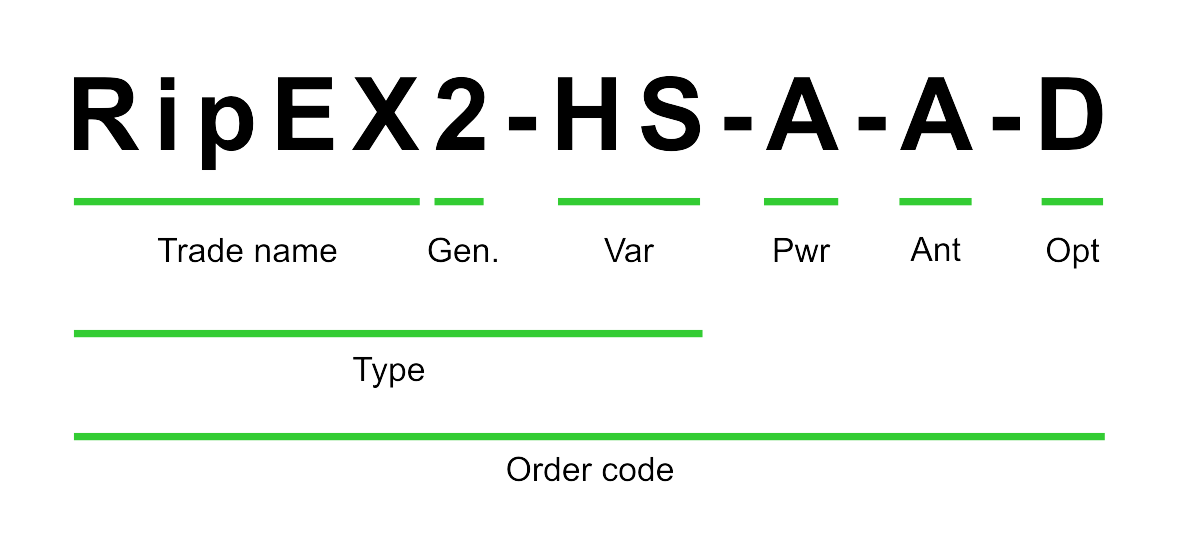
Trade name – trade and marketing name of the product. This name is used for all products within the same product family.
Possible values: RipEX
Gen – generation of the product of specific Trade name. The very first generation doesn’t have any number in this position.
Possible values: 2
Var – designation of product variant
Possible values:
HS – 19″ chassis, Hot Standby controller, 2x pow.supply, for 2x RipEX2 (excl.)
RD – 19″ chassis, without controller, 2x pow.supply, for 2x RipEX2 (excl.)
RS – 19″ chassis, without controller, 1x pow.supply, for 1x RipEX2 (excl.)
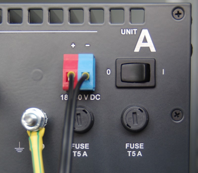
Pwr – power input
Possible values:
A – 100-240 VAC, 50-60 Hz
D – 36-60 VDC, positive grounding possible
E – 10-30 VDC
F – 18-30 VDC, positive grounding possible
Ant – antenna connectors
Possible values:
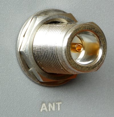
A – Var. HS: 1× N-female (Tx/Rx) – antenna switched for A and B unit
B – Var. HS: 2× N-female (Tx/Rx, Rx) – antennas switched for A and B unit
D – Var. HS or RD: 4× N-female (Tx/Rx, Rx; Tx/Rx, Rx) – no antenna switch, separate antennas for A and B unit
E – Var. RS: 2× N-female (Tx/Rx, Rx)
Opt – designation of internal option, if it is used
Possible values:
none
D – 1x internal duplexer, frequency details should be specified, for Var. RS + Ant. E or Var. HS + Ant. B
Type – specific product type for which type approvals like CE, FCC etc. are issued
Possible values:
RipEX2-HS (RipEX2-RD, RipEX2-RS in Code)
Order code – printed on Product label on the housing and used on Quotations, Invoices, Delivery notes etc.