Mount RipEX2 into cabinet (Section 4.3, “Mounting”).
Install antenna (Section 4.4, “Antenna installation”).
Install feed line (Section 4.5, “Antenna feed line”).
Ensure proper grounding (Section 4.6, “Grounding”).
Run cables and plug-in all connectors except from the SCADA equipment (Section 2.2, “Connectors”).
Apply power supply to RipEX2.
Connect configuration PC (Ripex2 “Connecting”).
Configure RipEX2.
Test radio link quality (e.g. using Monitoring tool or RSS ping).
Connect the SCADA equipment.
Test your application.
| Explosive atmospheres | |
|---|---|
The equipment should be used in hazardous locations under conditions according to Section 10.5, “Explosive atmospheres”. |
When cellular option is available
Enter the PIN code for the particular SIM card, if required (SETTINGS > Interfaces > Cellular > SIM1/SIM2).
Enable and Configure the Access Point Name (APN) (SETTINGS > Interfaces > Cellular > MAIN/EXT > Enable & Add/Edit Cellular profile).
Add default route 0.0.0.0/0 via WWAN (MAIN or EXT) (SETTINGS > Routing > Static) or other routing rule required.
No route is added automatically, required routes must be added manually.
Without such routes, unit will be connected to the cellular network, but not communicating with any other device/IP.
Save the changes.
Check functionality
SETTINGS > Interfaces > Cellular > Status > Show more (<)
DIAGNOSTICS > Tools > ICMP ping
DIAGNOSTICS > Statistics > Cellular statistic tables (Interface, State, Signal)
In case of any issues, download a detailed Diagnostic package (DIAGNOSTICS > Information > Diagnostic package), include all the information except User credentials and send it to support@racom.eu.
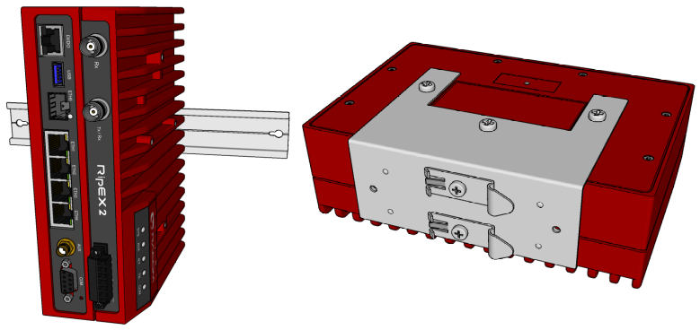
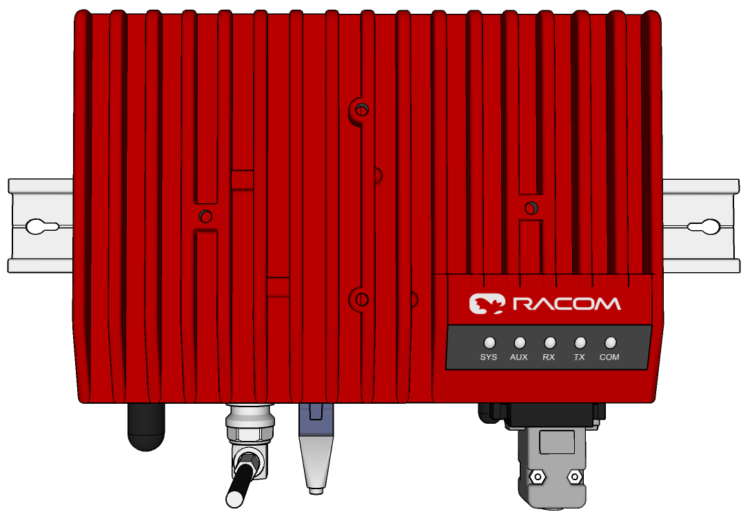
The radio modem RipEX2 is directly mounted using clips to the DIN rail. The mounting can be done lengthwise (recommended) or widthwise; in both cases with the RipEX2 lying flat. The choice is made by mounting the clips, one M4 screw per clip. RipEX2 is delivered with two clips, two screws and four threaded holes. Use solely the M4×5 mm screws that are supplied.

When tightening the screw on the clip, leave a 0.5 mm gap between the clip and the washer.
For vertical mounting to DIN rail, L-bracket (optional accessory) is used. Use solely the M4×5 mm screws that are supplied.
For more information see L-bracket.
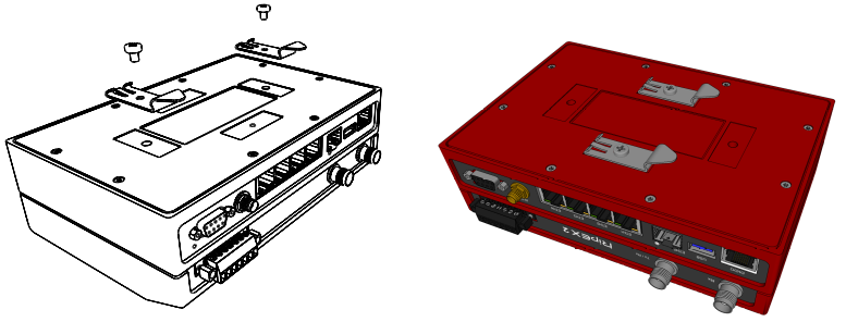
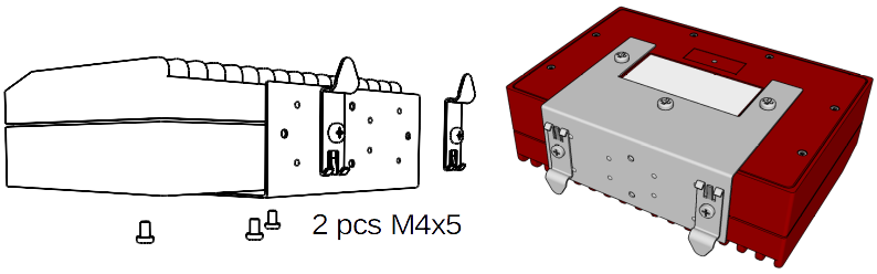
For flat mounting directly to the support you must use the Flat bracket (an optional accessory). Use solely the M4×5 mm screws that are supplied; tighten with torque 0.9 Nm.
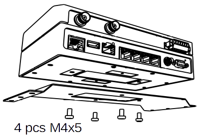
For more information see Flat-bracket.
The standard mounting for full-duplex operation is possible for surrounding temperatures bellow + 60 °C (see Table 9.1, “Technical parameters”), but it is recommended to use external passive cooler (e.g. installation in RipEX2-RS chassis) or keep the surrounding temperature bellow +35 °C for increasing of a long term reliability .
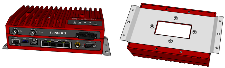
RipEX2 unit provides IP41 level of environmental protection. It is possible to reach higher level of protection IP52 (Limited dust ingress protection and protection from water spray < 15 degrees from vertical).
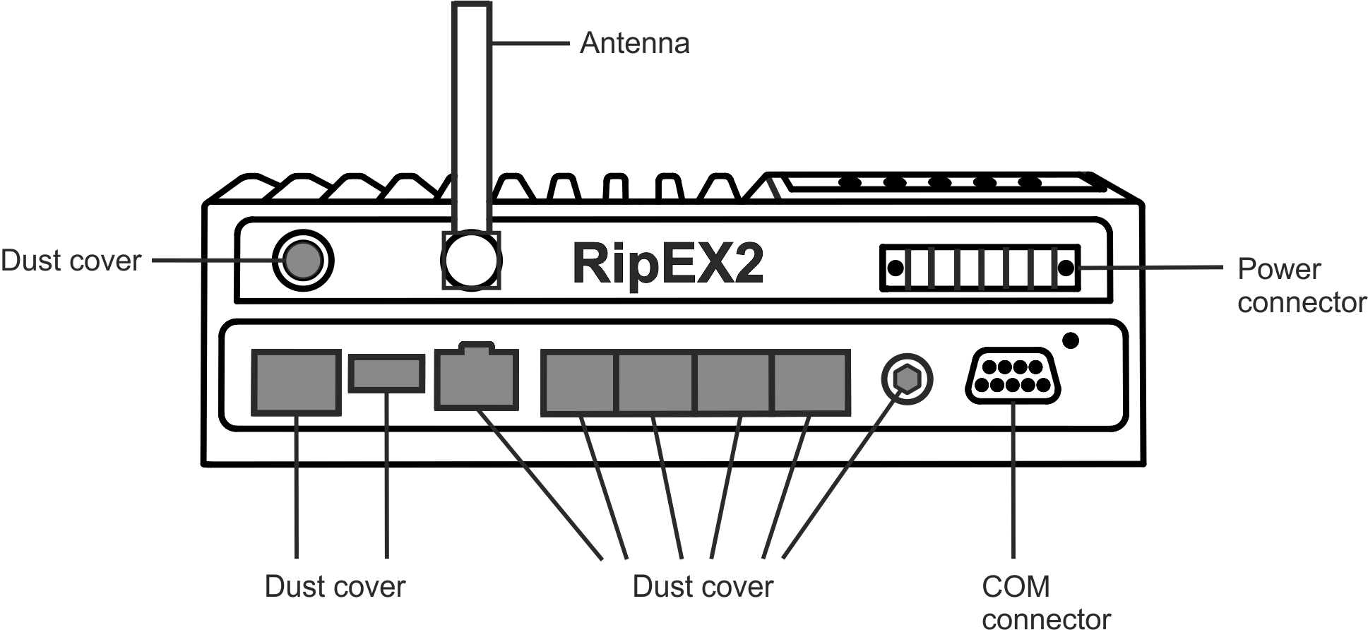
To obtain IP5x protection: plug in all connectors and cover unused ports (COM port does not need to be covered) with dust covers from the SET-RipEX2-IP5x.
To obtain IPx2 protection: RipEX2 unit must be physically installed with the connectors facing downward.
The type of antenna best suited for the individual sites of your network depends on the layout of the network and your requirements for signal level at each site. Proper network planning, including field signal measurements, should decide antenna types in the whole network. The plan will also determine what type of mast or pole should be used, where it should be located and where the antenna should be directed to.
The antenna pole or mast should be chosen with respect to the antenna dimensions and weight, to ensure adequate stability. Follow the antenna manufacturer’s instructions during installation.
The antenna should never be installed close to potential sources of interference, especially electronic devices like computers or switching power supplies. A typical example of totally wrong placement is mount a whip antenna directly on top of the box containing all the industrial equipment which is supposed to communicate via RipEX2, including all power supplies.
Additional safety recommendations
Only qualified personnel with authorization to work at heights are entitled to install antennas on masts, roofs and walls of buildings. Do not install the antenna in the vicinity of electrical lines. The antenna and brackets should not come into contact with electrical wiring at any time.
The antenna and cables are electrical conductors. During installation electrostatic charges may build up which may lead to injury. During installation or repair work all open metal parts must be temporarily grounded.
The antenna and antenna feed line must be grounded at all times.
Do not mount the antenna in windy or rainy conditions or during a storm, or if the area is covered with snow or ice. Do not touch the antenna, antenna brackets or conductors during a storm.
| Explosive atmospheres | |
|---|---|
Antenna has to be installed outside of the hazardous zone. |
The antenna feed line should be chosen so that its attenuation does not exceed 3 to 6 dB as a rule of thumb. Use 50 Ω impedance cables only.
The shorter the feed line, the better. If RipEX2 is installed close to antenna, the data cable can be replaced by an Ethernet cable for other protocols utilizing the serial port, see Section 7.1.4, “Terminal servers”.
Always follow the installation recommendations provided by the cable manufacturer (bend radius, etc.). Use suitable connectors and install them diligently. Poorly attached connectors increase interference and can cause link instability.
To minimize the odds of the transceiver and the connected equipment receiving any damage, a safety ground (NEC Class 2 compliant) should be used, which bonds the antenna system, transceiver, power supply, and connected data equipment to a single-point ground, keeping the ground leads short.
The RipEX2 radio modem is generally considered adequately grounded if the supplied flat mounting brackets are used to mount the radio modem to a properly grounded metal surface. If the radio modem is not mounted to a grounded surface, you should attach a safety ground wire to one of the mounting brackets or a screw on the radio modem’s casing.
It is strongly recommended to install an appropriate lightning protection system where the antenna cable enters the building.
| Note | |
|---|---|
All cablings, groundings and lightning protection must comply with the applicable standards and regulations. |
When the Full duplex operation is required, the Tx and Rx signals must be separated. The level of Tx to Rx signal attenuation must be at least 70 dB or better. Such a high level of Tx to Rx signal attenuation is typically achived by using a duplexer. Separate installation of Tx and Rx antenna can be used instead of using a duplexer.
RipEX2 uses standard connectors. Use only standard counterparts to these connectors.
You will find the pin-outs of connectors in Section 2.2, “Connectors”.
| Explosive atmospheres | |
|---|---|
Please note that connectors – or their individual pins – are connected to the housing. The housing is connected with the minus pin of the power connector. |
We do not recommend switching on power supply of the RipEX2 unit before connecting the antenna and other devices. Connecting the RTU and other devices to RipEX2 while powered increases the likelihood of damage due to the discharge of difference in electric potentials.

RipEX2 may be powered from any well-filtered 10 to 30 VDC power source. The supply must be capable of providing the required input for the projected RF output. The power supply must be sufficiently stable so that voltage doesn’t drop when switching from receiving to transmission, which takes less than 1.5 ms. To avoid radio channel interference, the power supply must meet all relevant EMC standards. Never install a power supply close to the antenna. Connector is internally connected to the casing of the RipEX2 unit.
| Explosive atmospheres | |
|---|---|
The unit must be powered with an intrinsic save power source for use in hazardous locations. |