RipEX2 is a radio modem platform renowned for overall data throughput in any real-time environment. RipEX2 radio modems are native IP devices, Software Defined with Linux OS that have been designed with attention to detail, performance and quality.
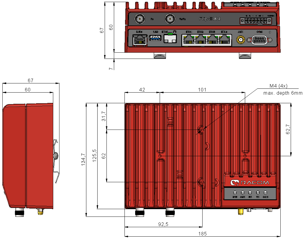
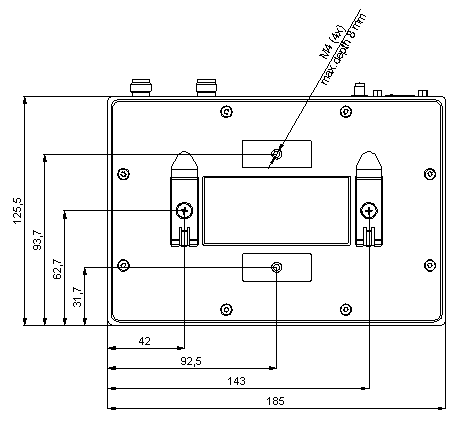
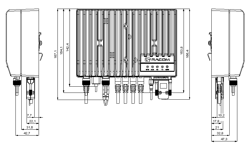
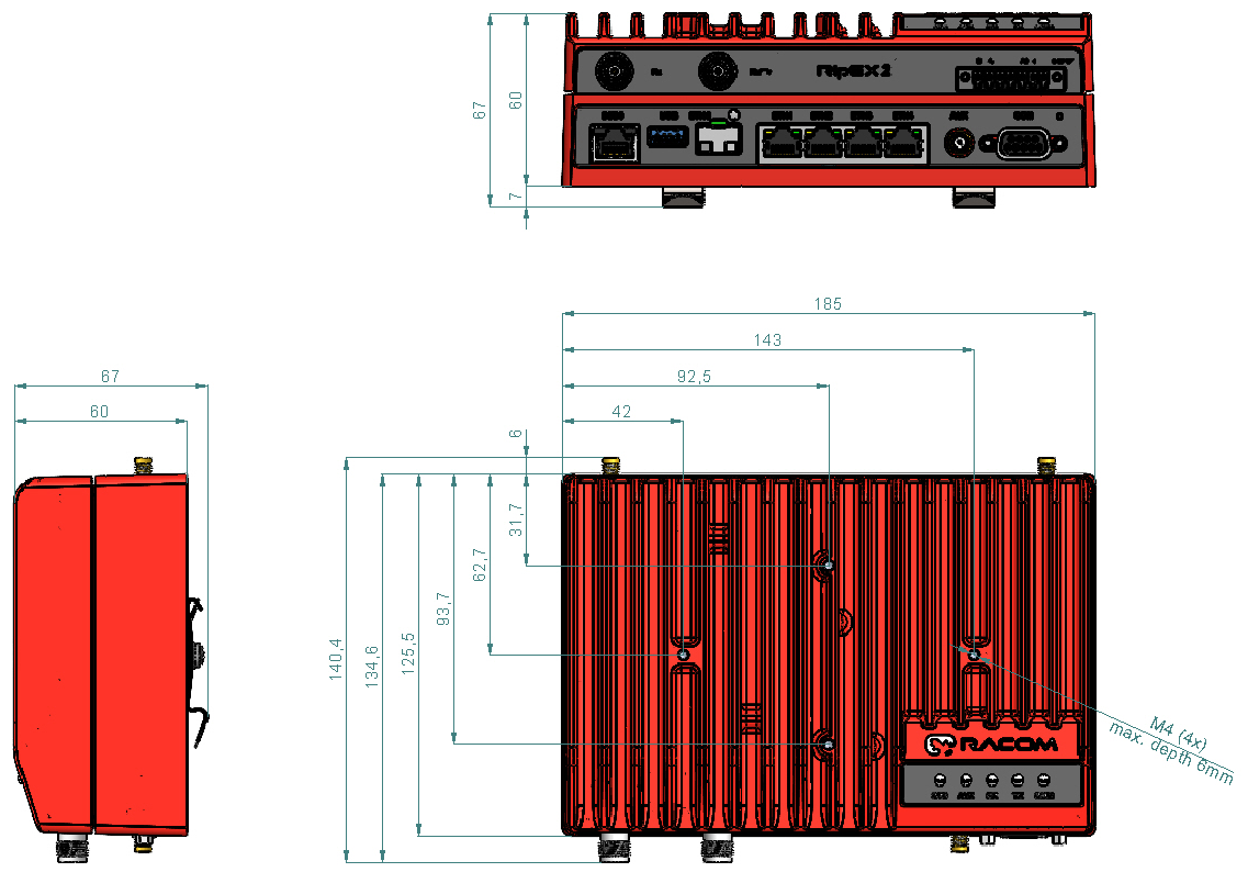
RipEX2 is built into a rugged die-cast aluminium casing that allows for multiple installation possibilities, see Section 4.3, “Mounting”.
| Explosive atmospheres | |
|---|---|
DO NOT HANDLE UNLESS THE AREA IS KNOWN TO BE NON-HAZARDOUS |

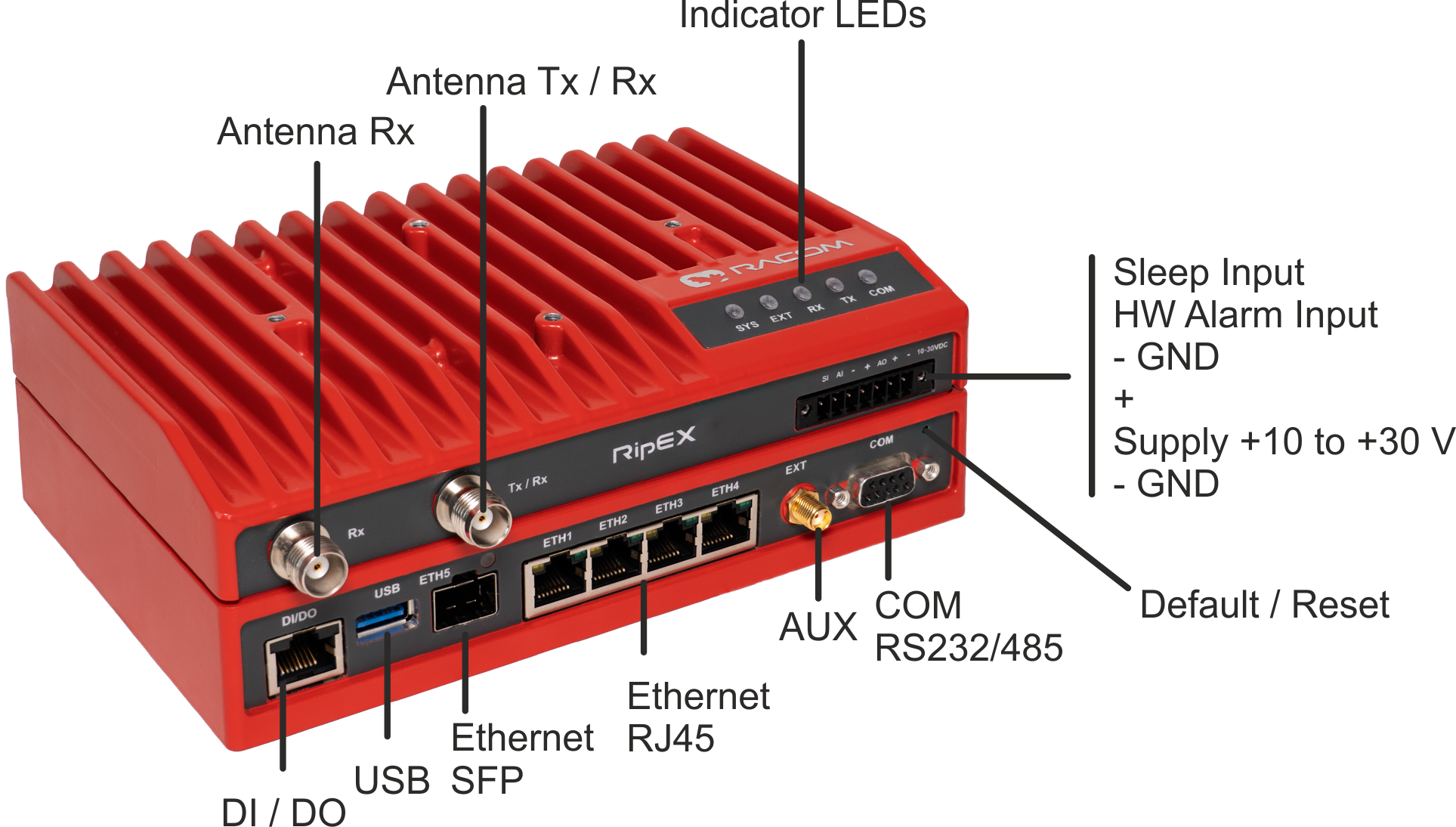
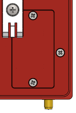
All connectors are located on the front panel. The upper side features a LED panel. The HW button is located on the front panel as well (close to the COM1, 2 connector).

| Explosive atmospheres | |
|---|---|
Do not manipulate the RipEX (e.g. plug or unplug connectors) unless powered down or the area is known to be non-hazardous. |

An antenna can be connected to RipEX2 via TNC female 50Ω connector.
RipEX2 is equipped with two connectors. The Tx/Rx connector will be used for common transmitting and receiving single antenna installation (even with different Rx and Tx frequencies).
Both Rx and Tx/Rx connectors for split installation (separated Tx and Rx antennas or full duplex operation with duplexer) – Rx for receiving and Tx/Rx for transmitting.
| Note | |
|---|---|
HW option RipEX2e (product variant ‘H’ and ‘J’) provides only Tx/Rx connector. |
| Warning | |
|---|---|
RipEX2 radio modem may be damaged when operated without an antenna or a dummy load. |
| Explosive atmospheres | |
|---|---|
Antenna has to be installed outside of the hazardous zone. |
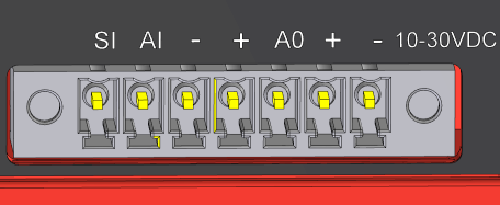
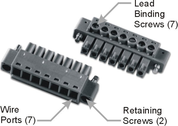
This rugged connector connects to a power supply and it contains control signals. A Plug with screw-terminals and retaining screws for power and control connector is supplied with each RipEX2. It is Tyco 7 pin terminal block plug, part No. 1776192-7, contact pitch 3.81 mm. The connector is designed for electric wires with a cross section of 0.5 to 1.5 mm2. Strip the wire leads to 6 mm (1/4 inch). Isolated cables should receive PKC 108 or less end sleeves before they are inserted in the clip. Insert the cables in the wire ports, tightening securely.
Tab. 2.1: Pin assignment
| Pin | Labeled | Signal |
|---|---|---|
| 1 | SI | SLEEP INPUT
|
| 2 | AI | HW ALARM INPUT
|
| 3 | − | −(GND) – for SLEEP IN, HW ALARM INPUT |
| 4 | + | +(POWER) – for HW ALARM OUTPUT |
| 5 | AO | HW ALARM OUTPUT open drain output max. 30 VDC, 1 A |
| 6 | + | + POWER (10 to 30 V) Undervoltage threshold 8.5 VDC Overvoltage threshold 41 VDC |
| 7 | − | − POWER (GND) |
Pins 3 and 7 are connected internally.
Pins 4 and 6 are connected
internally.
| Explosive atmospheres | |
|---|---|
The unit must be powered with an intrinsic save power source for use in hazardous locations. |
|
HW ALARM INPUT HW ALARM INPUT is a digital input. If grounded (e.g. by connecting to pin 3), an external alarm is triggered. |
 |
|
HW ALARM OUTPUT HW ALARM OUTPUT is a digital output. |
 |
POWER
The POWER pins labelled + and – serve to connect a power supply 10–30 VDC. The requirements for a power supply are defined in Section 4.9, “Power supply” and Chapter 9, Technical parameters.
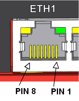
Standard RJ45 connectors for Ethernet connection. RipEX2 has 10/100/1000Base-T Auto MDI/MDIX interfaces so it can connect to 10 Mb/s, 100 Mb/s or 1000 Mb/s Ethernet network. The speed can be selected manually or recognized automatically by RipEX2. RipEX2 is provided with Auto MDI/MDIX function which allows it to connect over both standard and cross cables, adapting itself automatically.
Pin assignment
Tab. 2.2: Ethernet to cable connector connections
| Pin | Signal | Direct cable | Crossed cable | |
|---|---|---|---|---|
| 1 | TX+ | orange – white | green – white |
 |
| 2 | TX− | orange | green | |
| 3 | RX+ | green – white | orange – white | |
| 4 | — | blue | blue | |
| 5 | — | blue – white | blue – white | |
| 6 | Rx− | green | orange | |
| 7 | — | brown – white | brown – white | |
| 8 | — | brown | brown |
| Note | |
|---|---|
HW option RipEX2e (product variant ‘H’ and ‘J’) provides only ETH1 – ETH2 interfaces. |

ETH5 is a standard SFP slot for 10/100/1000 Mb/s Ethernet SFP modules, user exchangeable with maximal power consumption 1.25 W. Both fibre optic and metallic Ethernet SFP modules are supported. For optical both single and dual mode fibre optics Ethernet modules (= 2 or 1 fibers) can be used. CSFP modules are not supported. offers all mentioned types of SFP modules, tested to be RipEX2 compatible as a standard accessory.
The SFP status LED is located just next to the slot. It is controlled by SFP module. Its function is specific for each SFP module. The typical behavior is an indication the received signal from the fibre optic or metallic link to be within operational range.
| Important | |
|---|---|
It is strongly recommended to use a high quality SFP module with industry temperature range. The SFP modules listed in Accessories are thoroughly tested by and are guaranteed to function with RipEX2 units. It is possible to use any other SFP module, but cannot guarantee they will be completely compatible with RipEX2 units. |
| Note | |
|---|---|
HW option RipEX2e (product variant ‘H’ and ‘J’) does not provide ETH5 interface. |
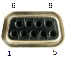
RipEX2 provides serial interface terminated by DSUB9F connector. RipEX2e and RipEX2 starting with version ‘F’ and ‘O’ provide two serial interfaces on the “COM” connector: COM1 and COM2. COM1 can be configured as RS232 or RS485. COM2 can only be used if COM1 is set to RS232 (not RS485).
RS232 of RipEX2 is a hard-wired DCE (Data Communication Equipment) device.
Equipment connected to the serial port of RipEX2 unit should be DTE (Data Terminal
Equipment) and a straight-through cable should be used. If a DCE device is connected to the
serial port of RipEX2, a null modem adapter or cross cable has to be
used.
RS485 of RipEX2 is not galvanic isolated and it is not terminated.
Tab. 2.3: COM pin description RipEX2 (except variant ‘F’ and ‘O’)
| DSUB9F | COM – RS232 | COM – RS485 | |||
|---|---|---|---|---|---|
| Pin | Signal | In/ Out | Signal | In/ Out |
 |
| 1 | CD | Out | — | ||
| 2 | RxD | Out | line B | In/Out | |
| 3 | TxD | In | line A | In/Out | |
| 4 | DTR | In | — | ||
| 5 | GND | GND | |||
| 6 | DSR | Out | — | ||
| 7 | RTS | In | — | ||
| 8 | CTS | Out | — | ||
| 9 | RI | Out | — | ||
RipEX2 keeps pin 6 DSR at the level of 0 (state ON, approx. +6.2 V) by RS232 standard permanently.
Tab. 2.4: COM pin description RipEX2e and RipEX2 (variant ‘F’ and ‘O’)
| DSUB9F | COM1 – RS232 | COM1 – RS485 | COM2 – RS232 (optional) | ||||
|---|---|---|---|---|---|---|---|
| Pin | Signal | In/ Out | Signal | In/ Out | Signal | In/ Out |
|
| 1 | CD | Out | — | — | |||
| 2 | RxD | Out | line B | In/Out | — | ||
| 3 | TxD | In | line A | In/Out | — | ||
| 4 | — | — | TxD | In | |||
| 5 | GND | GND | GND | ||||
| 6 | — | — | RxD | Out | |||
| 7 | RTS | In | — | — | |||
| 8 | CTS | Out | — | — | |||
| 9 | RI | Out | — | — | |||
Extension module ‘C’ (2 × RS232)
The 2nd and 3rd COM ports are available when the Extension module ‘C’ (2 × RS232) is installed. In such a case: The DI, DO connector is used as a connector for COM2 and COM3.
COM2 and COM3 parameters:
COM2: RS232 – 5 pin (RxD, TxD, GND, RTS, CTS) 300 b/s to 2 Mb/s
COM3: RS232 – 3 pin (RxD, TxD, GND) 2.4 kb/s to 921.6 kb/s
Tab. 2.5: DI, DO connector when used by Extension module ‘C’
Pin Signal In / Out 1 RxD COM3 Out 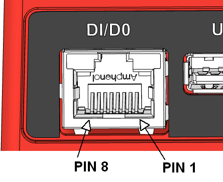
2 TxD COM3 In 3 GND 4 CTS COM2 Out 5 RTS COM2 In 6 GND 7 RxD COM2 Out 8 TxD COM2 In This interface is not compatible with RipEX2-HS.
If the RipEX2 unit is installed in the RipEX2-HS (Hot Standby chassis), the DI, DO interface is dedicated for the Hot standby operation.
| Note | |
|---|---|
Extension module ‘C’ allows to expand the unit by two additional RS232 serial ports. In the current firmware version it is not supported on HW which already provides COM2 in the basic version (Var. F and O.). |
RipEX2 uses USB 3.0, Host A interface. USB interface is wired as standard:
Tab. 2.6: USB A Pinout Cable Assembly
| Pin | Signal | Wire | |
|---|---|---|---|
| 1 | VBUS | Red |
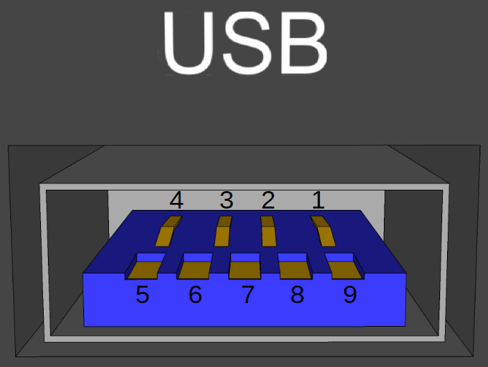 |
| 2 | D- | White | |
| 3 | D+ | Green | |
| 4 | GND | Black | |
| 5 | StdA_SSRX- | Blue | |
| 6 | StdA_SSRX+ | Yellow | |
| 7 | GND_DRAIN | GROUND | |
| 8 | StdA_SSTX- | Purple | |
| 9 | StdA_SSTX+ | Orange | |
| Shell | Shield | Connector Shell |
The USB interface is designed for the connection to an external ETH/USB adapter or a Wi-Fi adapter. They are optional accessories to RipEX2, for more details see www/ripex/accessories. The adapters are used for service access to web configuration interface of RipEX2 unit.
The USB connector also provides power supply (5 V / 0.5 A). It can be used to temporarily power a connected device, for instance a telephone. The USB connector should not be used as permanent source of power supply.
| Explosive atmospheres | |
|---|---|
Only USB equipments dedicated for hazardous locations shall remain connected permanently. |

EXT SMA female 50 Ohm connector is used for several purposes according to HW variant.
Standard basic model – the EXT is used as an synchronization signal input.
Input frequency range 1 Hz (PPS) – 25 MHz
Input signal level >200 mVp-p @ 220R, up to 5V TTL levels
Time synchronisation from outer source will be implemented in future FW releases.
RipEX2 can be equipped with an internal G – Extension GPS (GNSS) module (see details). The GPS module is used for time synchronization of the NTP server inside RipEX2. In this case the EXT connector serves for connecting the GPS antenna:
active antenna
3.3 VDC supply
| Note | |
|---|---|
Interface AUX was renamed to EXT (FW version 2.0.13.0. and newer). |
| Note | |
|---|---|
For the RipEX2 version with narrowband LTE (cellular modules ‘M’ and ‘O’), the EXT connector is used to connect the antenna. |
| Note | |
|---|---|
HW option RipEX2e (product variant ‘H’ and ‘J’) does not provide EXT interface. |
Tab. 2.7: Digital Inputs and Outputs
| Pin | Description | Signal | |
|---|---|---|---|
| 1 | DI1+ | Digital input (differential) – Positive – (P) |
|
| 2 | DI1- | Digital input (differential) – Negative – (N) | |
| 3 | GND | Ground | |
| 4 | DO1 |
Digital Output 1 | |
| 5 | DO2 |
Digital Output 2 | |
| 6 | GND | Ground | |
| 7 | DI2 | Digital Input 2 | |
| 8 | DI3 | Digital Input 3 |
Digital Outputs:
Open drain output max. 30 VDC, 0.2 A
Isolated differential digital input:
Input voltage difference (P-N) > 1.9 VDC Logic “H”
Input voltage difference (P-N) < 1.1 VDC Logic “L”
Maximum differential voltage 30 V
Digital inputs:
Schmitt-triggered inverted input
Pull below 1.1 VDC to activate (1.1 VDC / 1.9 VDC threshold hysteresis)
Max. 30 VDC
If the RipEX2 unit is installed in the RipEX2-HS (Hot Standby chassis), the DI, DO interface is dedicated for the Hot standby operation.
| Note | |
|---|---|
HW option RipEX2e (product variant ‘H’ and ‘J’) does not provide DI, DO interface. |
| Note | |
|---|---|
These Digital Inputs and Outputs cannot be used if the unit is equipped with the ‘C’ Expansion module providing additional serial ports. |
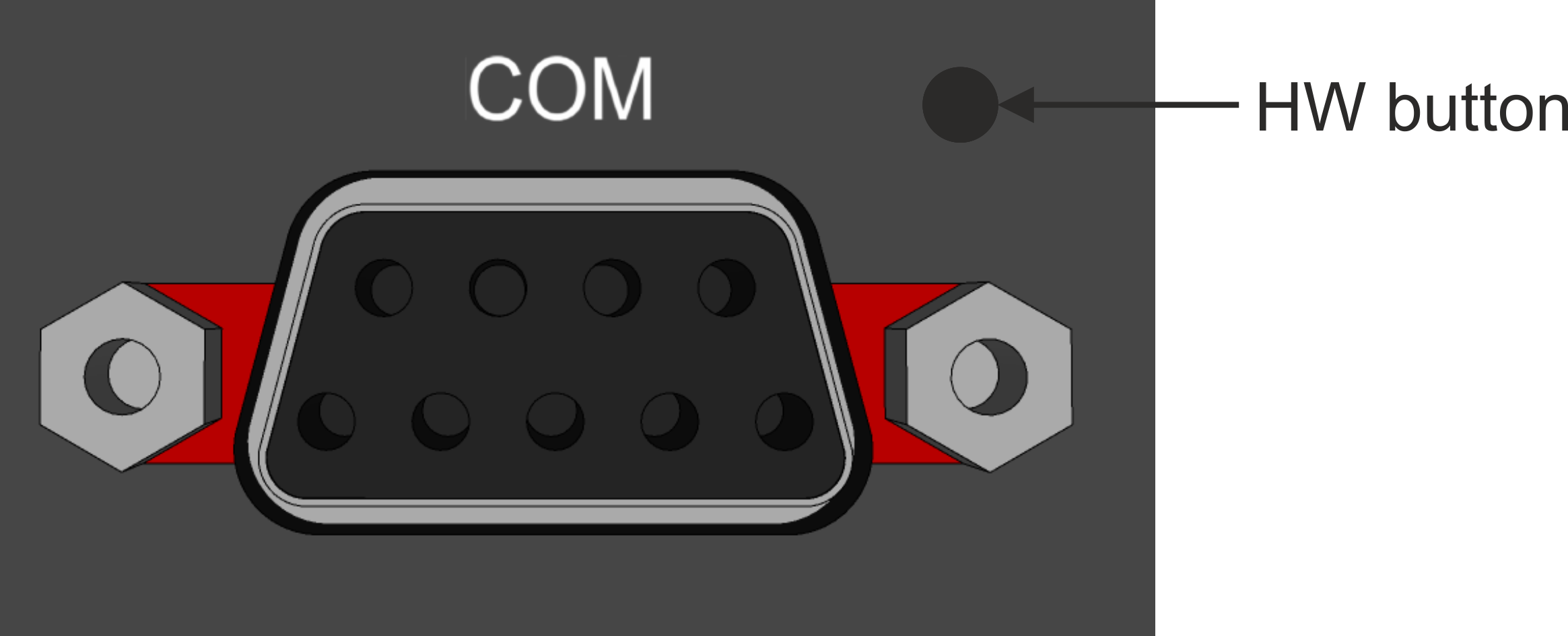
HW button is placed on the right side of COM interface.
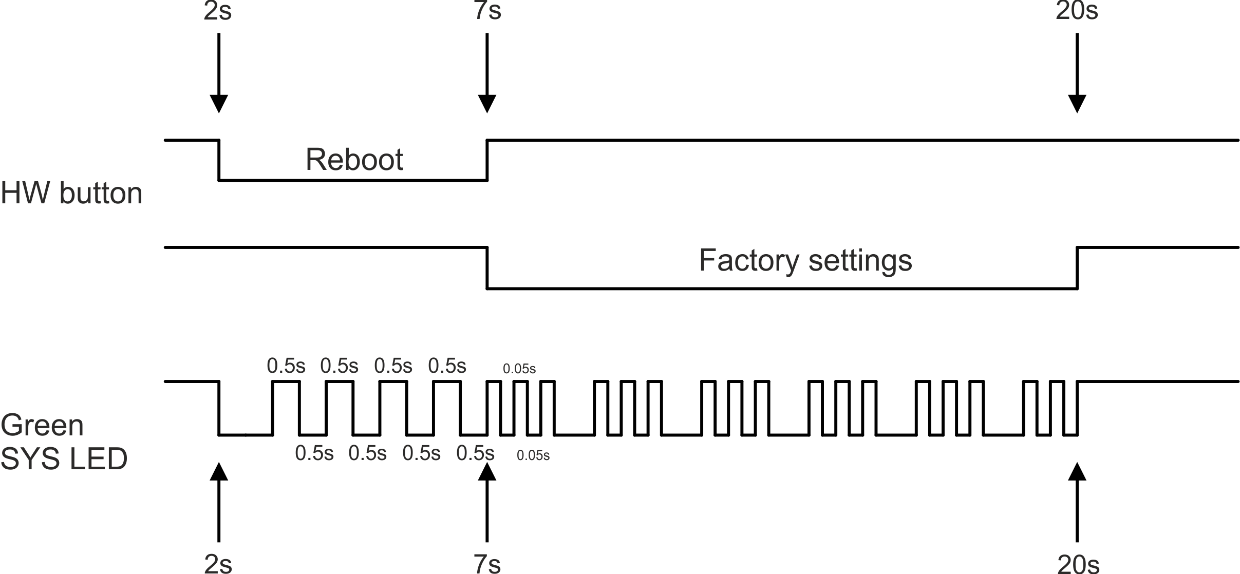
HW button operation
Press less than 2 seconds – Nothing happens
Press from 2 up to 7 seconds – Reboot is performed on button release
Press from 7 up to 20 seconds – Factory settings are performed on button release
Press more than 20 seconds – Nothing happens
RipEX2 radio modem can be delivered with the cellular extension.
RipEX2 radio modem equipped with the LTE cellular module has two additional SMA antenna connectors mounted on the opposite side than radio antenna connectors.
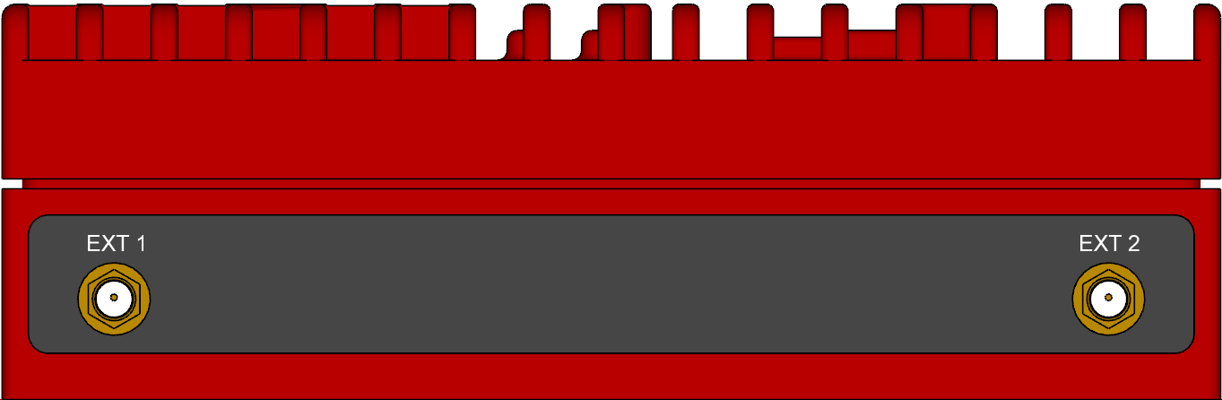
It is recommended to use both antennas (Rx diversity) for the LTE connection. In case of using only one antenna, attach it to the EXT1 connector. The EXT1 connector is used for both transmitting and receiving, or for single-antenna setups. The EXT2 connector is specifically for Rx diversity.
| Note | |
|---|---|
For the RipEX2 version with narrowband LTE (cellular modules ‘M’ and ‘O’), the EXT connector is used to connect the antenna. |
RipEX2 radio modem can be delivered with the Wi-Fi extension.
RipEX2 radio modem equipped with the Wi-Fi module has two additional SMA antenna connectors mounted on the opposite side than radio antenna connectors. See chapter 2.3.1 for the corresponding picture of the antenna connectors.
It is possible to use either one or two antennas. Antenna configuration needs to be setup accordingly in the EXT1 and EXT2 antenna configuration parameters in the Settings > Interfaces > Wi-Fi menu.
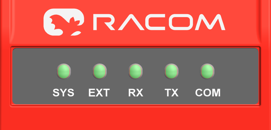
Tab. 2.8: Key to LEDs
| LED | Colour | Status | Function |
|---|---|---|---|
| SYS | Green | Permanently lit | System OK |
| Flashing – period 500 ms | Reset button pushed | ||
| Three fast (50 ms) flashes – pause (500 ms) | Reset button factory reset | ||
| Flashing regularly – period 2000 ms | Sleep mode activated | ||
| Red | Permanently lit | Alarm | |
| Flashing regularly – period 500 ms | Serious system error | ||
| Orange | Permanently lit | Unit booting | |
| Three fast (75 ms) flashes | USB flash disc inserted | ||
| Flashing fast (75ms) – period 1000 ms | Interaction with USB flash disc | ||
| Green / Orange | Flashing regularly – period 300 ms | FW activation – do not shut down the device | |
| EXT | Green | Permanently lit |
Activity of mPCIe connected equipment (like GPS fix, LTE connected, …) |
| Red | Permanently lit |
Alarm of mPCIe connected equipment | |
| Table of Signal levels for individual services for cellular interface | |||
| Table of GNSS activity | |||
| Rx | Green | Permanently lit | Receiver is synchronized to a packet |
| Yellow | Permanently lit, or flashing in 1 sec intervals | Rx mode of operation – High resiliance (strong interfering signals – above -45 dBm – are present within the frequency band) | |
| Tx | Red | Permanently lit | Transmitting to radio channel |
| COM1 ,2 | Green | Permanently lit | Data receiving |
| Yellow | Permanently lit | Data transmitting | |
- Alarm
An Alarm is triggered by any event with severity Error or higher (see Section 8.4, “Events”).
- High resilience mode
LED signalization of receiver High resilience mode can be enabled/disabled by configuration item ADVANCED > Interfaces > Radio > Radio parameters > High resilience LED indication (see Section 7.1.2.8.2, “Radio channel – advanced ” for details).

Trade name – trade and marketing name of the product. This name is used for all products within the same product family.
Possible values: RipEX
Gen. – generation of the product of specific Trade name. The very first generation does not have any number in this position.
Possible values: none, 2
Band – frequency band and sub-band
Possible values:
1A: 135–175 MHz
2A: 215–240 MHz
3A: 285–335 MHz
3B: 335–400 MHz
4A: 400–470 MHz
4B: 450–520 MHz
8A: 803–897 MHz
9A: 860–960 MHz
Ext. – Extension module embedded in mPCIe slot. The module cannot be changed later on.
Possible values:
N – not used (the only option for RipEX2e)
W – Extension cellular module; Part No.: mPCIe-W
Bands W – 4G/3G/2G, GlobalR – Extension cellular module; Part No.: mPCIe-R
Bands R – LTE Cat M1/NB1/NB2, LatAm, Europe (incl. 410 MHz, 450 MHz)S – Extension cellular module; Part No.: mPCIe-S
Bands S – LTE Cat M1/NB1/NB2, GlobalG – Extension GPS (GNSS) module; Part No.: mPCIe-GPS
F – Extension Wi-Fi module; Part No.: mPCIe-WIFI
![[Note]](/images/radost/images/icons/note.png)
Note Only one option for mPCIe slot is possible
Legacy values:
E – Extension cellular module E; Part No.: mPCIe-E.
P – Extension cellular module P; Part No.: mPCIe-P.
A – Extension cellular module A; Part No.: mPCIe-A.
M – Extension cellular module M Part No.: mPCIe-M.
O – Extension cellular module O; Part No.: mPCIe-O.
C – Extension module 2× RS232; Part No.: mPCIe-COMS.
Var. – designation of product variant. This variant is fixed in unit HW and cannot be changed later on.
Possible values:
F – RipEX2, Data encryption possible. COM2 available. Directly succeeds ‘E’ version.
H – RipEX2e (essential version), Data encryption possible. COM2 available.
J – RipEX2e (essential version), Data encryption never possible (AES256, IPsec, OpenVPN never possible). COM2 available.
O – RipEX2, Data encryption never possible (AES256, IPsec, OpenVPN never possible). COM2 available. Directly succeeds ‘N’ version.
Legacy values:
C – RipEX2e, processor without HW encryption support. Discontinued from 8/2023
D – RipEX2e, processor without HW encryption support. Encryption features will never be possible. Discontinued from 8/2023
E – RipEX2, Data encryption possible. Discontinued from 8/2024
N – RipEX2, Data encryption never possible (AES256, IPsec, OpenVPN never possible). Discontinued from 8/2024
X*– RipEX2, processor with HW encryption support. Discontinued from 12/2022
SW keys – if unit is ordered with SW keys, all keys are specified in this bracket. SW key can be ordered independently for specific S/N anytime later on.
Possible values (subject to availability of a respective SW feature with a particular HW configuration):
Master – enables all functionalities of all possible SW feature keys, excl. Ex; Part No.: RipEX2-SW-MASTER, RipEX2e-SW-MASTER
Protocols – enables Radio protocols (Flexible, Base driven); Part No.: RipEX2-SW-PROTOCOLS
Dynamic routing – enables Dynamic routing (Babel, OSPF, BGP, Link management, PPPoE); Part No.: RipEX2-SW-DYNAMIC-ROUTING
Speed – enables 256QAM, ACM, Channels > 50kHz, Full duplex, RipEX2 only; Part No.: RipEX2-SW-SPEED
Power – enables RF power 40 dBm PEP; Part No.: RipEX2-SW-POWER
Security – enables IPsec, OpenVPN, RADIUS, Multiple users; Part No.: RipEX2-SW-SECURITY
SFP – enables SFP interface, RipEX2 only; Part No.: RipEX2-SW-SFP
COM2 – enables COM2 interface, RipEX2e, RipEX2 variant ‘F’ and ‘O’ only; Part No.: RipEX2-SW-COM2
Ex – authorization for use RipEX2 in hazardous location II 3G Ex ic IIA T4 Gc. Part No.: RipEX2-Ex (Note: Ex keys are available only for units produced after 1st of January 2022)
Region – used for countries where specific restrictions are required. Available only on special request when ordering. If used, it is indicated in bracket along with the SW keys.
Possible values:
US – USA, Allowed freq. according to FCC part 90
RipEX2 – 1A: 150.8 – 156.2475, 157.1875 – 161.575, 161.775 – 161.9625, 162.0375 – 170.0 MHz; Reg. ID: 1A-FCC_Part_90
RipEX2 – 4A: 4A: 406.1 – 454.0, 456 – 462.5375, 462.7375 – 467.5375, 467.7375 – 470.0 MHz; Reg. ID: 4A-FCC_Part_90RU – Russia, Allowed freq. according to Russian regulations
RipEX2 – 1A: 146.0 – 174.0 MHz; Reg. ID: 1A-Russia
RipEX2 – 4A: 403.0 – 410.0, 433.0 – 450.0 MHz; Reg. ID: 4A-Russia
RipEX2 – 4A: 433.0 – 450.0 MHz; Adjusted product label; Reg. ID: 4-RussiaBR – Brazil, 6.25 kHz channel not allowed
RipEX2 – 4A: Additional sticker (Anatel 16763) on product and paper box; Reg. ID: 4A-BrazilMX – Mexico, Additional sticker on product and paper box
Type – specific product type
Possible values:
RipEX2-1
RipEX2-3
RipEX2-4
Code – part of order code which is printed on Product label on the housing (SW keys are not HW dependent and can be ordered later on, so they are not printed on Product label).
Order code – the complete product code, which is used on Quotations, Invoices, Delivery notes etc.
In order to find out the correct Order code, please use E-shop.
* The processor included in the unit uses an encryption module listed as 5A002 a.1 in the
Regulation (EU) 2021/821, setting up a Community regime for the control of exports, transfer,
brokering and transit of dual-use items. Units are subject to export control when exporting
outside the European union, according to national, EU and US law (ECCN 5A002 a.1), see https://policy.trade.ec.europa.eu/help-exporters-and-importers/exporting-dual-use-items_en.
In the case of export from the country where the units were delivered by
, the exporter must inform of the new country of delivery. X was
under production until XII/2022