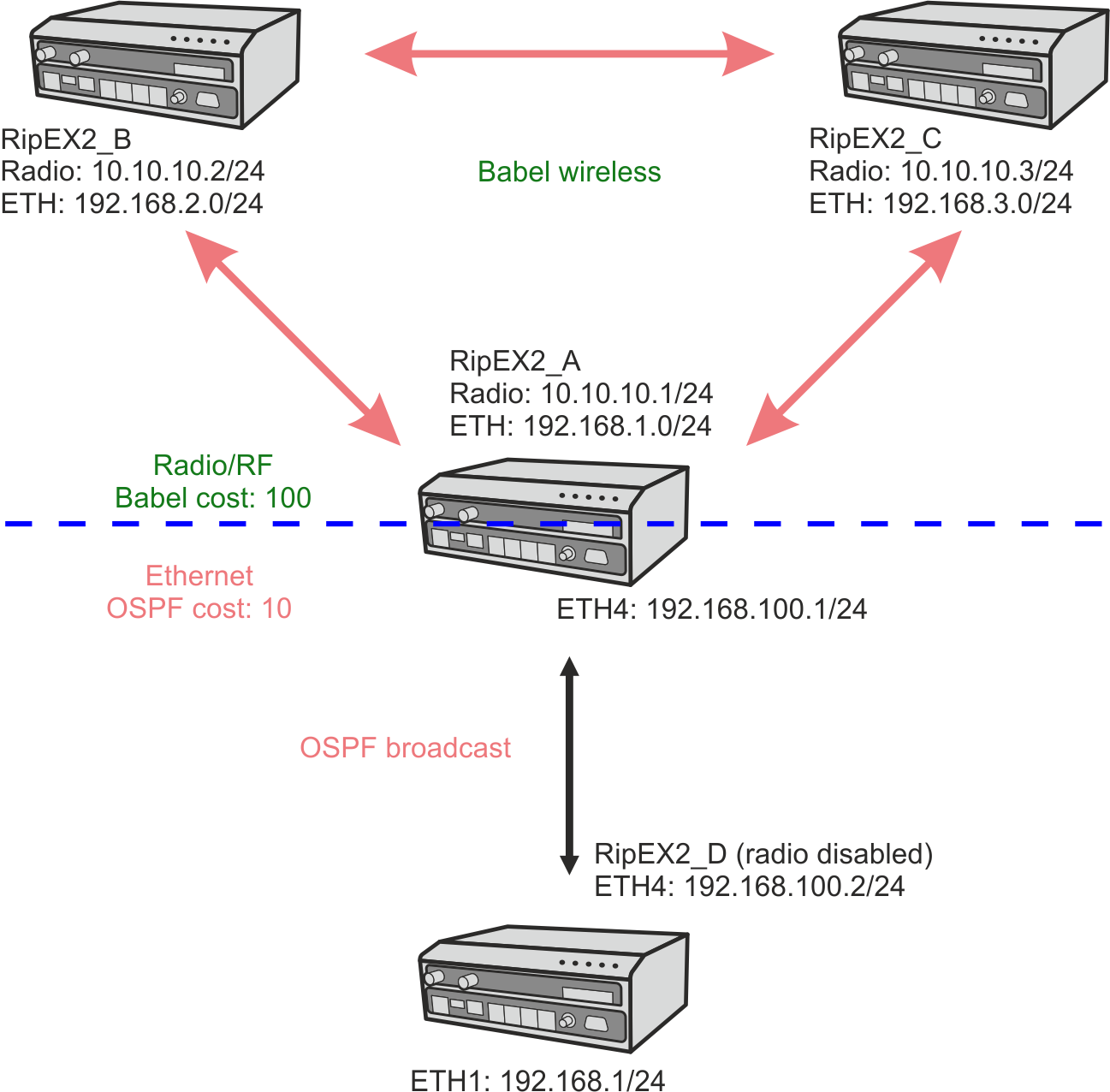
The sixth example shows a network combining Babel and OSPF. OSPF is configured in RipEX_A and RipEX_D units, whereas Babel is configured in RipEX_A, B and C. These two protocols are neighboring in one Autonomous System Border Router “ASBR” (RipEX_A) which divides the whole network into two parts. Bandwidth optimized Babel on the Radio segment and standardized, widely-used and fast OSPF on the Ethernet segment.
These two parts are interconnected together utilizing default gateways. E.g., Radio network is completely routed by Babel and all other routes are routed to ETH4 interface of RipEX_A via a default gateway rule (0.0.0.0/0). In other words, there is no other export of routing rules.
Without dynamic protocols, all routes would need to be filled manually and statically.
Startup configurations are taken from first example. See the required changes below. It is required to change RipEX_A and RipEX_D settings only.
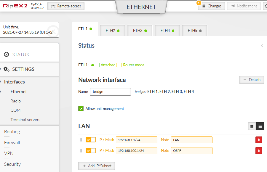
Add a 2nd IP/Mask to the “bridge” Ethernet interface. A new 192.168.100.1/24 IP address will be used for Ethernet connection to RipEX_D and OSPF. You could also detach a particular ETH port and assign this IP to this designated port.
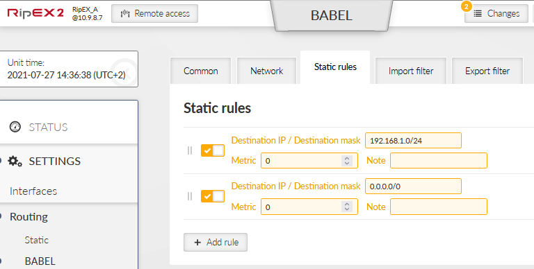
Add a new “default route” to current Babel Static rules. This default route will be used between OSPF and Babel network segments.
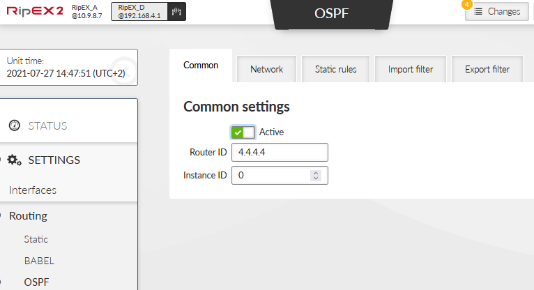
Go to the OSPF Routing menu and enable OSPF dynamic protocol. The Router ID is shared among all dynamic protocols.
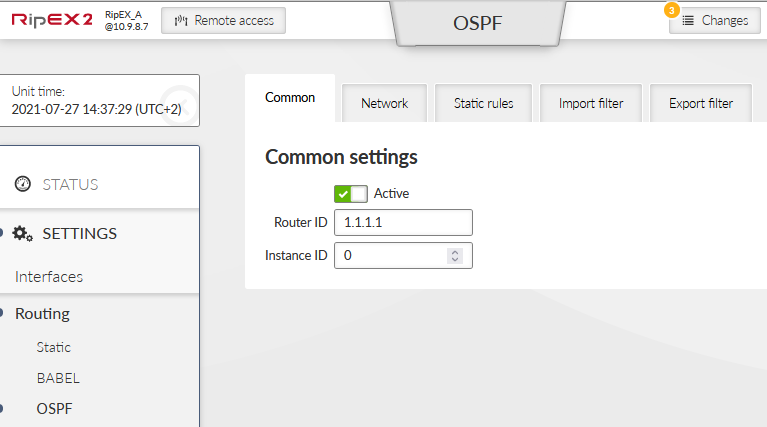
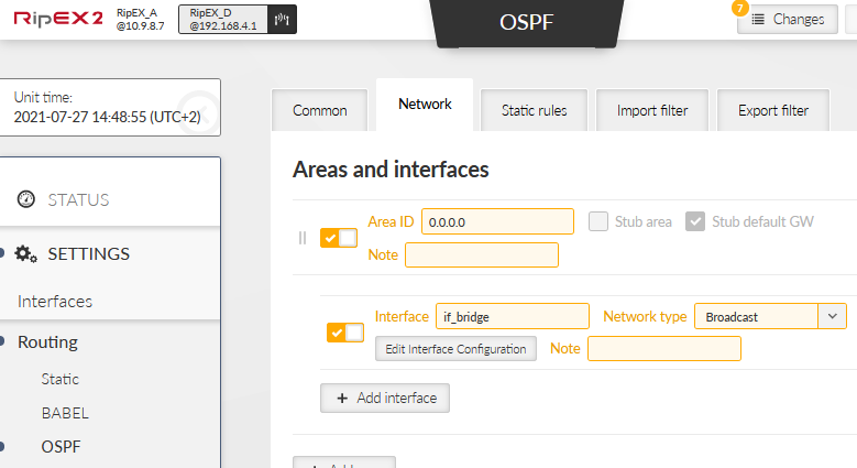
Create a new OSPF Area ID 0.0.0.0 (so called “backbone area” which has to be used in OSPF and all other areas must be directly connected to it).
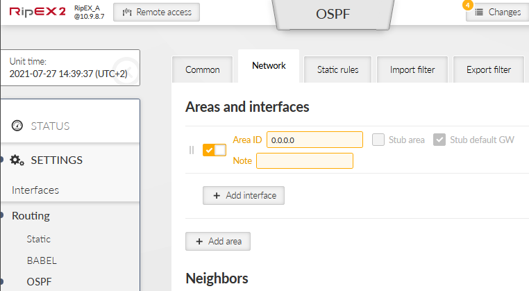
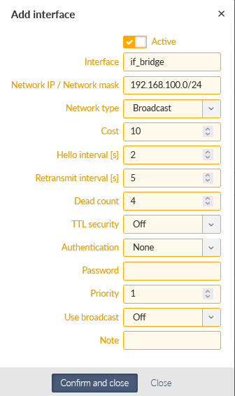
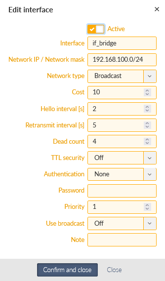
Add a new interface under this backbone Area. Change the following parameters:
Interface | if_bridge |
Network IP/Mask | 192.168.100.0/24 |
Network type | Broadcast
|
Hello interval | 2
|
Other parameters stay in default values.
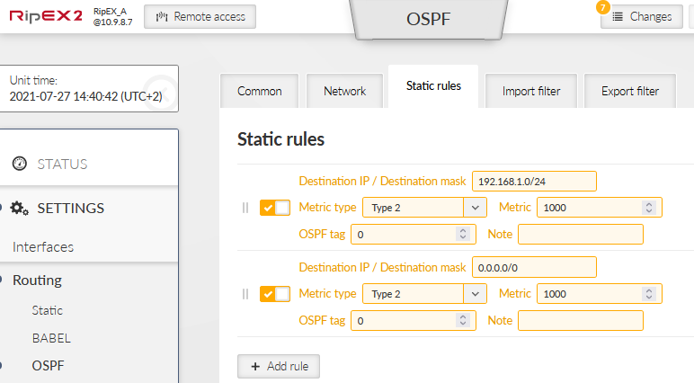
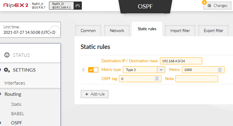
Go to the Static rules tab and add two rules.
192.168.1.0/24
Metric type 2
Metric 1000
0.0.0.0/0
Metric type 2
Metric 1000
It is not important if the metric type is “1” or “2” in this example, but it is used to distinguish rules which came to OSPF from Babel (and cannot be exported back to Babel).
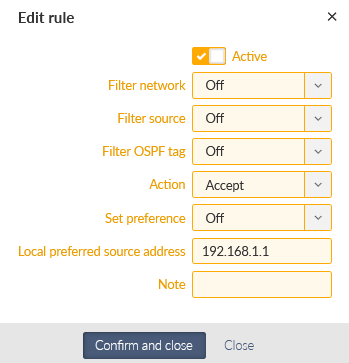
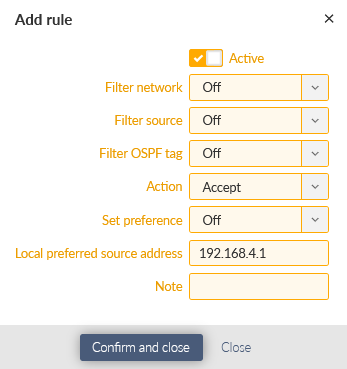
Go to the last required tab and add an Import filter with the following settings. Only the “Local preferred source address” is to be filled – with local ETH IP 192.168.1.1 so that packets generated in this RipEX2 unit use 192.168.1.1 as their Source IP.
There is no change required in RipEX_B and RipEX_C units.
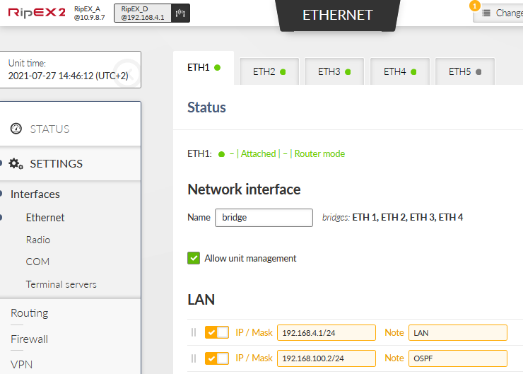
Add a 2nd IP/Mask to the “bridge” Ethernet interface. A new 192.168.100.2/24 IP address will be used for Ethernet connection to RipEX_A and OSPF. You could also detach a particular ETH port and assign this IP to this designated port.
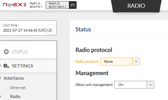
Disable the Radio protocol so there is no Radio/RF communication, only Ethernet connection to RipEX_A.
Disable Babel protocol.
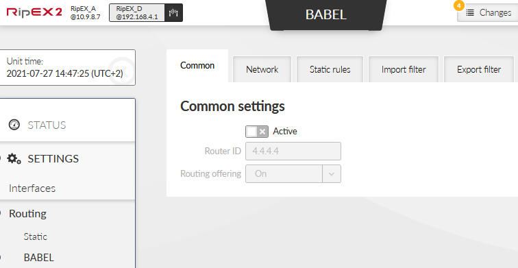
Enable OSPF with the same Router ID 4.4.4.4.
Add one OSPF interface within a new backbone Area ID 0.0.0.0.
Interface | if_bridge |
Network IP/Mask | 192.168.100.0/24 |
Network type | Broadcast |
Hello interval | 2 |
Details:
Add one Static rule so that local 192.168.4.0/24 is propagated through OSPF protocol. Set the same Metric type (2) and Metric (1000) as in RipEX_A.
Finally, add one Import filter with Local preferred source address equal to 192.168.4.1.
You can attach your laptops to RipEX2 units and do some PING tests. You can also configure some SCADA protocol traffic simulation.
The “issue” with testing this scenario on the desk is that each radio can hear each other (except RipEX_D). Thus, it is not possible to force Babel and Radio channel to send traffic via a repeater by default and only if this fails, sending data directly. The traffic always uses a direct connection. Only if you had some attenuators or you use it in the field, there should be situations in which traffic goes via two radio hops.
Also, the OSPF and Babel are neighboring in one ASBR router (RipEX_A) – so if you turn off RipEX_A, then RipEX_D loses its connection to the radio segment (and vice versa). There is no other way.
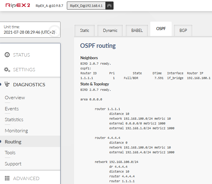
So, check the correct routing is set and used in all routers and also check the ping works among all units. Typical outputs you should see are:
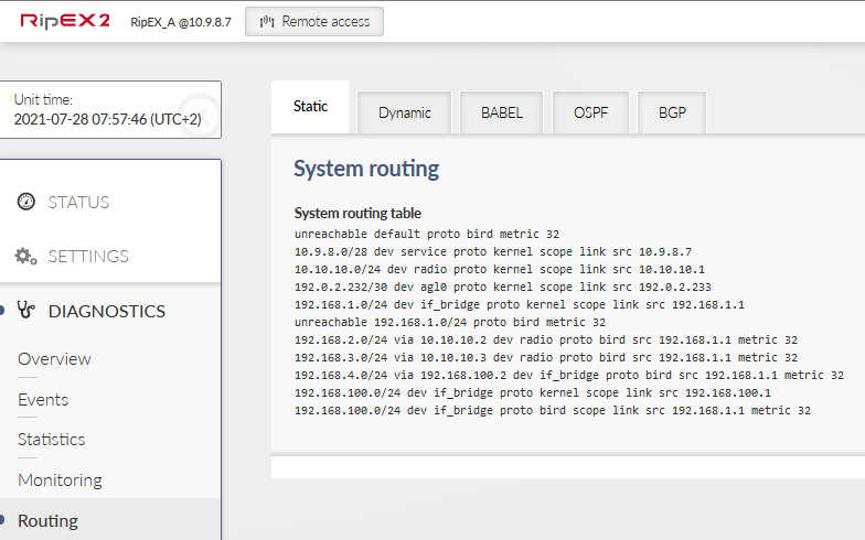
RipEX_A should have /24 routes to all LANs behind every other RipEX2 in this example.
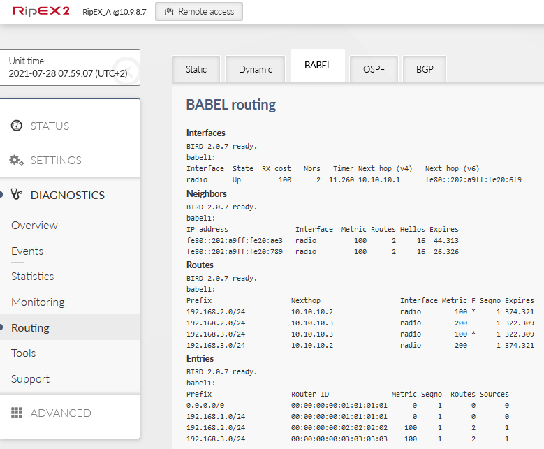
In the Babel output, you should see two neighbors and a direct metric to each with a cost of 100.
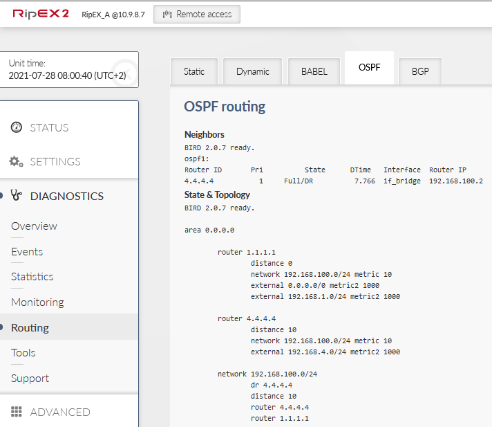
There should be one 4.4.4.4 neighbor with state either Full/DR or Full/BDR.

RipEX_B should have routes to its Radio neighbors (192.168.1.0/24 and 192.168.3.0/24) with Metric equal to 100 and one default gateway rule back to RipEX_A (also with a Metric equal to 100). The same is for RipEX_C.
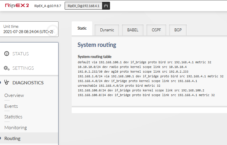
RipEX_D should have a /24 link to 192.168.1.0 subnet via its if_bridge interface and gateway 192.168.100.1 (RipEX_A) and a default gateway (also 192.168.100.1) for the whole radio segment.
All the routes are obtained via OSPF. There is no Babel configured.