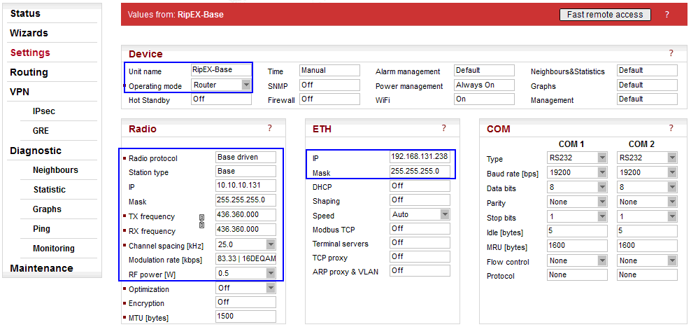
Parameters:
| Unit name | “RipEX-Base” |
| Operating mode | “Router“ (IPsec cannot be used in the Bridge mode) |
| Radio protocol | “Base Driven“ (The protocol can also be set as “Flexible”, but this example utilizes the Base Driven Protocol, BDP) |
| Station type | “Base” (detailed configuration in Fig. 3.2 RipEX-Base Radio protocol settings ) |
| IP/Mask | “10.10.10.131/24” (common subnet for all RipEX units in this example) |
| TX/RX frequency | “436.360.000 MHz” (configure any frequency, but the same among all RipEX units – simplex or duplex scenarios are both possible) |
| Channel spacing | “25 kHz” (configure any spacing, but this must be the same for all units) |
| Modulation rate | “83.33 | 16DEQAM” (use the same “type” for all units, but otherwise, configure as preferred) |
| RF power (W) | “0.5 W” (set the minimum possible RF power for tests using dummy loads on your desk – laboratory tests) |
| ETH IP/Mask | “192.168.131.238/24” (set the Ethernet IP/Mask) |
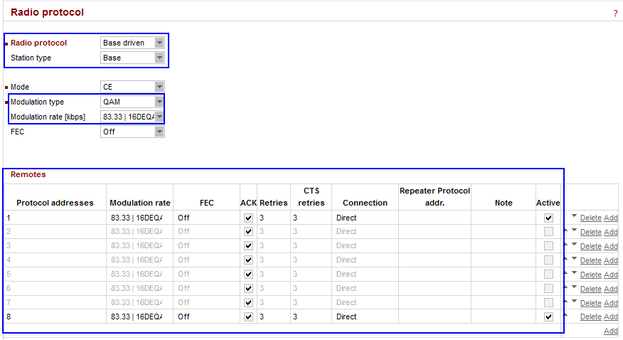
Parameters:
| Radio protocol | “Base driven” |
| Station type | “Base” |
| Modulation type | “QAM” (must be the same among all RipEX units) |
| Modulation rate | “83.33 kbps | 16DEQAM” (the default modulation rate) |
| Remotes | 8 remote units are configured, but only 2 of them are activated due to the simplicity of this example. The Modulation rate can be set for each link individually, as well as FEC, ACK, Retries or CTS retries. The connection is “Direct” for all units. |
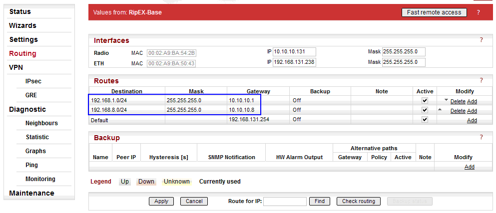
The Peer IP address can either be the Radio IP or Ethernet IP (if the remote end-point is RipEX). Correct routing rules must be configured for remote end-point accessibility, i.e. 192.168.1.1/32 and 192.168.2.1/32. Otherwise, RipEX-Base does not know a route to the other RipEX’s Ethernet IPs.
In the following step (IPsec configuration), interconnection of local and remote subnets via IPsec tunnels will be configured. Correct routing MUST be configured, otherwise, the traffic between remote Ethernet subnets will be filtered and discarded. I.e. for each planned remote subnet which should be reachable via IPsec, a correct routing must be set.
If the IPsec is down, there are automatic firewall rules blocking such traffic to avoid unencrypted data being sent from the RipEX unit. In our example, if the tunnel is down, RipEX-Base blocks all the traffic coming from the 192.168.131.0/24 network to 192.168.1.0/24 and/or 192.168.8.0/24 networks. This traffic can only be forwarded if an IPsec tunnel is used (so it’s up and running).
192.168.1.0/24 via 10.10.10.1 (connection to RipEX1-remote)
192.168.8.0/24 via 10.10.10.8 (connection to RipEX8-remote)
Once correct routing rules are connected on remote units, Ethernet-to-Ethernet connectivity is ready.
There is also a Default gateway configured (192.168.131.254). This route can be omitted completely if not required for any other purpose (e.g. accessibility of this unit via Ethernet from other subnets).
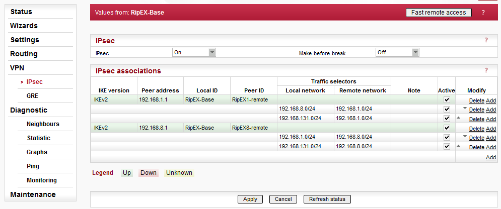
In Fig. 3.4, two IPsec associations are already configured and running. See Fig. 3.5 for the tunnel configuration. Both tunnels are configured in the same way.
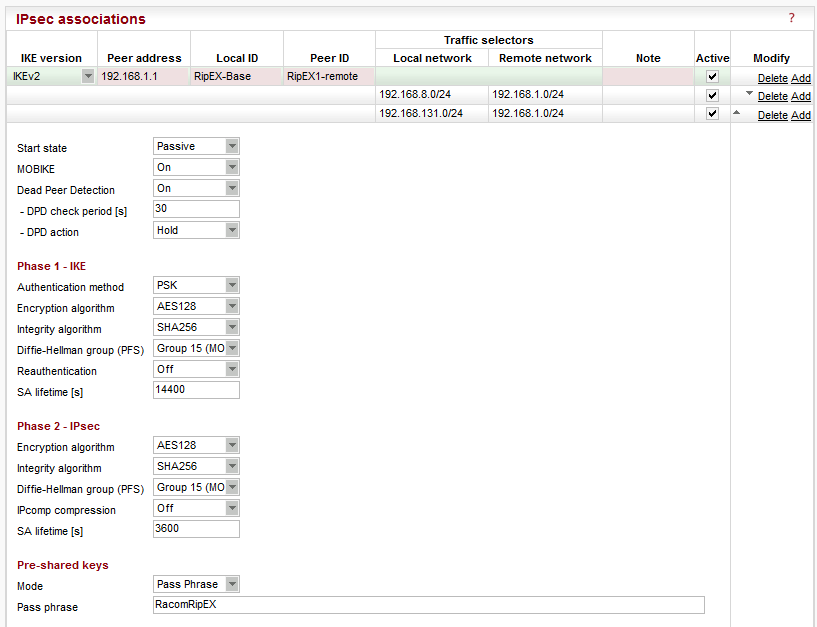
Parameters:
| IKE version | “IKEv2” (IKEv1 is also implemented) |
| Peer address | “192.168.1.1” (Ethernet IP address of “RipEX1-remote”) |
| Local ID | “RipEX-Base” |
| Remote ID | “RipEX1-remote” |
| Traffic selectors | “192.168.8.0/24 (local) <-> 192.168.1.0/24” (a selector for RipEX1-remote and RipEX2-remote connectivity over IPsec) “192.168.131.0/24 (local) <-> 192.168.1.0/24” (a basic selector for Ethernet to Ethernet accessibility over IPsec) |
| Start state | “Passive” (it waits for incoming connections from remote units) |
| MOBIKE | “On” (default) |
| Dead Peer Detection | “On” (check every 30 seconds and if there is no accessibility of remote end-point, close the connection and wait for re-establishment, i.e. “Hold” option) |
| Phase 1 – IKE | |
| Authentication method | “PSK” |
| Encryption algorithm | “AES128” (default) |
| Integrity algorithm | “SHA256” (default) |
| PFS | “Group 15” (default) |
| Reauthentication | “Off” (default) |
| SA lifetime [s] | “14400” (default) |
| Phase 2 – IPsec | |
| Encryption algorithm | “AES128” (default) |
| Integrity algorithm | “SHA256” (default) |
| PFS | “Group 15” (default) |
| IPcomp compression | “Off” (default) |
| SA lifetime [s] | “3600” (default) |
| Pre-shared keys | |
| Mode | “Pass phrase” (default) |
| Pass phrase | “RacomRipEX” (can be configured as required, but must be the same on both units) |
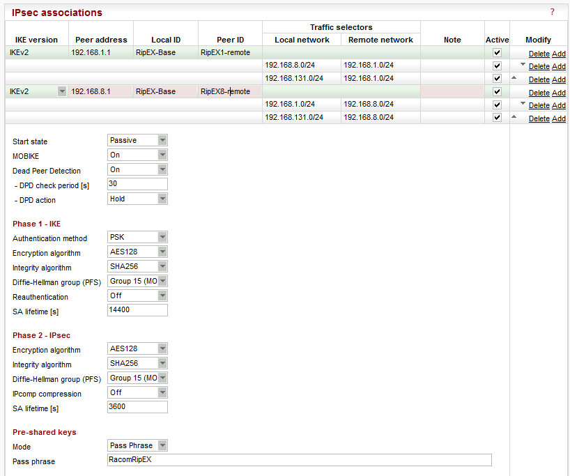
The second tunnel has the same parameters except for:
| Peer address | “192.168.8.1” (“RipEX8-remote” Ethernet IP) |
| Peer ID | “RipEX8-remote” |
| Traffic selectors | “192.168.1.0/24 (local) <-> 192.168.8.0/24” (a selector for RipEX1-remote and RipEX2-remote connectivity over IPsec) “192.168.131.0/24 (local) <-> 192.168.8.0/24” (a basic selector for Ethernet to Ethernet reachability over IPsec) |
NOTE: The start states should not be “Start” at both tunnel end-points, because it might happen that both end-points will try to initiate the connection at the same time and thus create and delete SAs until resolved. Do not use a “Passive” mode at both end-points – no tunnel would be initiated at all.
Once configured and applied, the tunnels need the remote units to be configured as well, otherwise the tunnels cannot be established.