RipEX is a widely configurable compact radio modem, more precisely a radio IP router. All you have to do to put it into operation is to connect it to an antenna and a power supply and configure it using a PC (tablet, smart phone) and a web browser.
RipEX access defaults: username: admin, password: admin
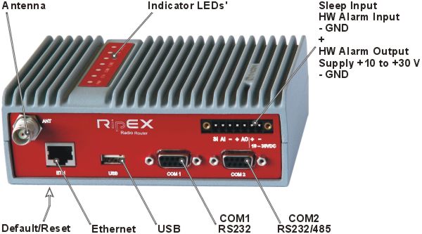
Ethernet
RipEX default IP is 192.168.169.169/24, so set a static IP 192.168.169.x/24 on your PC, power on the RipEX and wait approximately 48 seconds for the RipEX OS to boot. Connect your PC to RipEX‘s ETH interface, start your browser and type https://192.168.169.169 in the address line.
Before attempting to do any configuration, make sure your RipEX is the only powered-up unit around. Since all units coming from factory share the same default settings ex factory, you could be accessing a different unit over the air without being aware of it.
USB/ETH adapter
When accessing over the optional “XA” USB/ETH adapter, your PC will get its IP settings from the built-in DHCP server and you have to type https://10.9.8.7 in your browser. You do not need to worry about other RipEX units, you will be connected to the local unit in all cases.
Wifi adapter
When accessing over the optional “W1” Wifi adapter, connect your PC (tablet, smart phone) to the RipEX Wifi AP first. Its default SSID is “RipEX + Unit name + S/N”
Your PC will get its IP settings from the built-in DHCP server and you have to type http://10.9.8.7 in your browser. Remaining steps are the same and you do not need to worry about other RipEX units, since you will be connected to the local unit in all cases.
SCADA radio network step-by-step
Building a reliable radio network for a SCADA system may not be that simple, even when you use such a versatile and easy-to-operate device as the RipEX radio modem. The following step-by-step checklist can help you to keep this process fast and efficient.
Design your network to ensure RF signal levels meet system requirements.
Calculate and estimate the network throughput and response times when loaded by your application.
Perform a bench-test with 3-5 sets of RipEX‘s and SCADA equipment (Chapter 4, Bench test).
Design the addressing and routing scheme of the network (Chapter 2, RipEX in detail and RipEX App notes – Address Planning).
Preconfigure all RipEX‘s (Section 4.4, “Basic setup”).
Install individual sites
Mount RipEX into cabinet (Section 6.1.1, “DIN rail mounting”).
Install antenna (Section 6.2, “Antenna mounting”).
Install feed line (Section 6.3, “Antenna feed line”).
Ensure proper grounding (Section 6.4, “Grounding”).
Run cables and plug-in all connectors except from the SCADA equipment (Section 5.2, “Connectors”)
Apply power supply to RipEX
Test radio link quality (Section 4.5, “Functional test”).
Check routing by the ping tool (Section 7.6.3, “Ping”) to verify accessibility of all IP addresses with which the unit will communicate.
Connect the SCADA equipment
Test your application