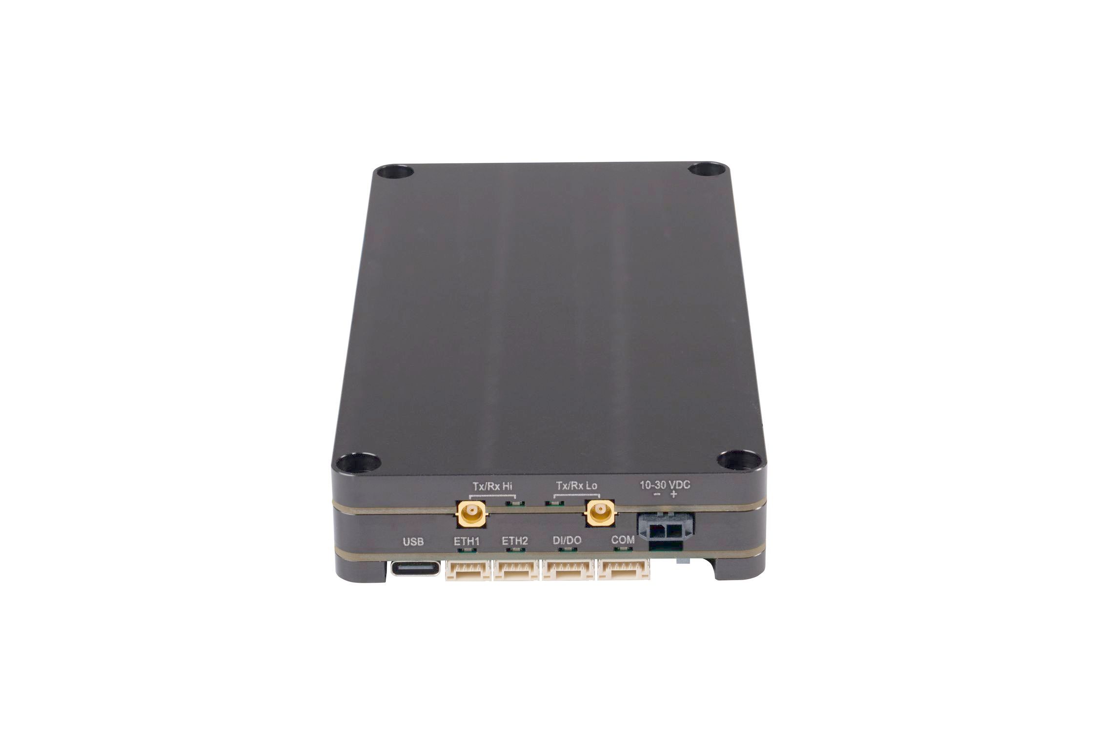
WaSP is a compact, high-performance radio modem, tailored for wireless surveillance applications. Designed for fast, secure and reliable data transfer in mission-critical operations, its lightweight, embedded form makes it ideal for UGVs (Unmanned Ground Vehicles) and UAVs (Unmanned Aerial Vehicles), where every gram and watt matters.
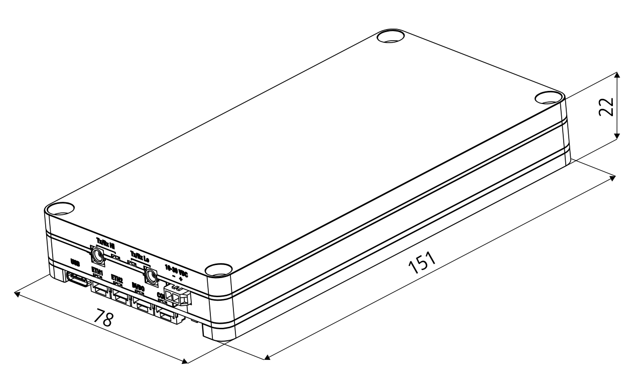
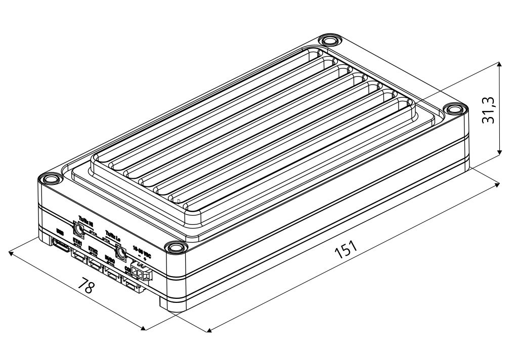
![[Note]](/images/radost/images/icons/note.png) | Note |
|---|---|
The 31.3 mm dimension can be changed according to the height of the passive cooler used. |
All connectors and LEDs are located on the front panel.
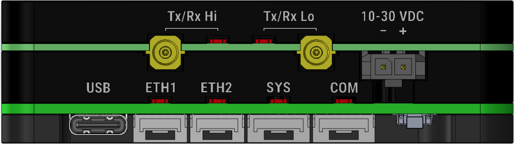
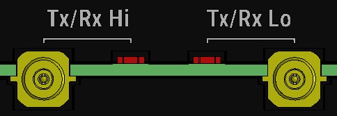
An antenna can be connected to WaSP via MCX female 50Ω connector.
WaSP is equipped with two connectors. Both connectors are used for Tx/Rx according to SW setting of the radio. The left connector is used for higher frequencies band antenna connection, the right for lower frequencies band antenna.
![[Warning]](/images/radost/images/icons/warning.png) | Warning |
|---|---|
WaSP radio modem may be damaged when operated without an antenna or a dummy load. |
This rugged connector connects to a power supply.
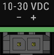
POWER
The POWER pins labelled + and – serve to connect a power supply 10–30 VDC. The requirements for a power supply are defined in Section 2.3, “Power supply” and Chapter 6, Technical parameters.
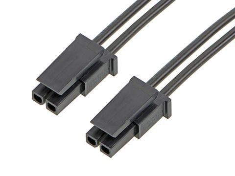
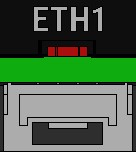
JST-GH connectors for Ethernet connection. WaSP has 10/100Base-T Auto MDI/MDIX interfaces so it can connect to 10 Mb/s or 100 Mb/s Ethernet network. The speed can be selected manually or recognized automatically by WaSP. WaSP is provided with Auto MDI/MDIX function which allows it to connect over both standard and cross cables, adapting itself automatically.
Pin assignment
Tab. 1.2: Ethernet to cable connector connections
| Pin | Signal | Direct cable | Crossed cable | |
|---|---|---|---|---|
| 1 | Rx− | green | orange |
 |
| 2 | RX+ | green – white | orange – white | |
| 3 | TX− | orange | green | |
| 4 | TX+ | orange – white | green – white |
WaSP provides serial interface terminated by JST-GH connector.
RS232 of WaSP is a hard-wired DCE (Data Communication Equipment) device.
Equipment connected to the serial port of WaSP unit should be DTE (Data Terminal
Equipment) and a straight-through cable should be used. If a DCE device is connected to the
serial port of WaSP, a null modem adapter or cross cable has to be
used.
WaSP uses USB 2.0. USB interface is wired as standard USB-C:
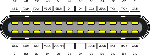
The USB interface is designed for the connection to an external ETH/USB adapter or a Wi-Fi adapter. They are optional accessories to WaSP. The adapters are used for service access to web configuration interface of WaSP unit.
The USB connector also provides power supply (5 V / 0.5 A). It can be used to temporarily power a connected device, for instance a telephone. The USB connector should not be used as permanent source of power supply.
The digital input and output interface connector is located below the SYS status LED.
Tab. 1.4: Digital Inputs and Outputs
| Pin | Description | Signal | |
|---|---|---|---|
| 1 | SI | Sleep Input |
 |
| 2 | AI | Alarm Input | |
| 3 | GND | Ground | |
| 4 | AO |
Alarm Output | |
| 5 | GND | Ground |
Digital Outputs:
Open drain output max. 30 VDC, 0.2 A
Digital inputs:
Schmitt-triggered inverted input
Pull below 1.1 VDC to activate (1.1 VDC / 1.9 VDC threshold hysteresis)
Max. 30 VDC
HW button is placed on the right side of COM interface.
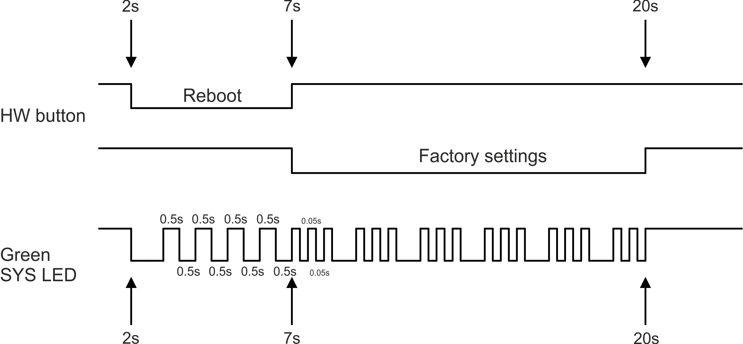
HW button operation
Press less than 2 seconds – Nothing happens
Press from 2 up to 7 seconds – Reboot is performed on button release
Press from 7 up to 20 seconds – Factory settings are performed on button release
Press more than 20 seconds – Nothing happens
Tab. 1.5: Key to LEDs
| LED | Colour | Status | Function |
|---|---|---|---|
| SYS | Green | Permanently lit | System OK |
| Flashing – period 500 ms | HW button pushed | ||
| Three fast (50 ms) flashes – pause (500 ms) | HW button factory reset | ||
| Flashing regularly – period 2000 ms | Sleep mode activated | ||
| Red | Permanently lit | Alarm | |
| Flashing regularly – period 500 ms | Serious system error | ||
| Orange | Permanently lit | Unit booting | |
| Three fast (75 ms) flashes | USB flash disc inserted | ||
| Flashing fast (75 ms) – period 1000 ms | Interaction with USB flash disc | ||
| Green / Orange | Flashing regularly – period 300 ms | FW activation – do not shut down the device | |
|
Tx/Rx Hi Tx/Rx Lo | Green | Permanently lit | Receiver is synchronized to a packet |
| Red | Permanently lit | Transmitting to radio channel | |
| COM | Green | Permanently lit | Data receiving |
| Yellow | Permanently lit | Data transmitting |
- Alarm
An Alarm is triggered by any event with severity Error or higher (see Section 5.4, “Events”).
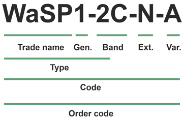
Trade name – trade and marketing name of the product. This name is used for all products within the same product family.
Possible values: WaSP
Gen. – generation of the product of specific Trade name.
Possible values: 1
Band – frequency band and sub-band
Possible values:
2C: 200 – 470 and 700 – 960 MHz
Ext. – Extension module embedded in mPCIe slot.
Possible values:
N – not used
Var. – designation of product variant. This variant is fixed in unit HW and cannot be changed later on.
Possible values:
A – casing without cooling radiator
B – casing with cooling radiator
Type – specific product type
Possible values:
WASP1-2
Code – part of order code which is printed on Product label on the housing (SW keys are not HW dependent and can be ordered later on, so they are not printed on Product label).
Order code – the complete product code, which is used on Quotations, Invoices, Delivery notes etc.
The WaSP unit uses frequency hopping listed as 5A001.b.3.b in the Regulation (EU)
2021/821, setting up a Community regime for the control of exports, transfer, brokering and
transit of dual-use items. Units are subject to export control when exporting outside the
European union, according to national, EU and US law (ECCN 5A001.b.3.b),
see
https://policy.trade.ec.europa.eu/help-exporters-and-importers/exporting-dual-use-items_en.
In the case of export from the country where the units were delivered by
, the exporter must inform of the new country of delivery.