The Serial Communication Channels menu enables the setup of all SCC parameters available, ranging from physical layer parameters to the network interface ones. It is divided into CNI, Protocol and Extensions submenus.
The CNI menu is identical for all channel types. For CNI menu description see chapter Chapter 25, CNI-channel to node interface.
This submenu contains both low-level channel parameters (bit rate, handshaking, etc.) and access module configuration (type of protocol supported and its parameters).
From MORSE main menu type SPe Enter Enter:
SCCs:
    n     m     g    b   p8   i   s  XRC D G  o
(0)RS232 ASYNC  SW  19200N81  5 1600 --- D 0 MARS-A
(1)RS232 ASYNC  SW  19200N81  5 1600 --- D 0 MARS-A
(2)RS232 ASYNC  SW 115200N81  5 1600 --- D 0 ASYNC LINK
(3)RS232 ASYNC  SW  19200N81  5 1600 --- D 0 MARS-A
type 1 Enter
Serial Communication Channels:
i(n)t:RS232  (m)ode:ASYNC   dia(g):SW
(b)it/s:19200  (p)ar:NONE  (8)bit:ON  s(T)op:OFF  fr(A)gs:7+9/16
RX (i)dle:5 RX buf (s)ize:1600
TX idl(e):OFF
Handshake: (X)on/Xoff:OFF  (R)TS:OFF  (C)TS:OFF
C(D):ON  (G):0000
pr(o)tocol MARS-A parame(t)ers
ext clocks t(x):OFF  (r)x:OFF sync (w)ord:7E7E
SC(M):0131
| i(n)t: | — the interface type
| ||||||||||
| (m)ode: | — link layer low level mode (part of SCM), it is automatically derived from the selected protocol
| ||||||||||
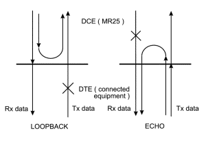
| dia(g): | — diagnostic mode (part of SCM)
| ||||||||||
| (b)it/s:19200 | — transmission speed in bits per second, to be written in hundreds (type b1152 to get 115200, or b6 to get 600) | ||||||||||
| (p)ar: | — parity setting (part of SCM)
| ||||||||||
| (8)bit:ON | — number of data bits (part of SCM)
| ||||||||||
| s(T)op:ON | — the stop bit length consists of the optional part | ||||||||||
| fr(A)gs:7+9/16 | — this part of the stop bit is present permanently. It’s length is adjustable by exchanging the number 7 by 0 to 7, the resulting length is from 9/16 to 16/16 period. The total length of stop bit can be set using both parameters s(T)op and fr(A)gs in interval 0.563 to 1.000 or 1.563 to 2.000 bits. The double port SCC2+3 in MR400 series can use the parameter s(T)op only. The fr(A)gs parameter has the value 16/16 permanently. The total length can be set to 1 or 2 bits. | ||||||||||
| RX (i)dle:5 | — number of idle characters received from connected equipment before the RX buffer is closed. The lowest possible setting is recommended (5 characters in most cases). | ||||||||||
| RX buf (s)ize:1600 | — the maximum size of the receiving buffer on the relevant SCC port – the possible maximum value is 1600 bytes | ||||||||||
| TX idl(e):OFF |
| ||||||||||
| Handshake: |
| ||||||||||
| pr(o)tocol: | — selects the protocol supported by the access module, the list can be changed in new firmware versions: Select new protocol: (n)-NONE (B)-ALLEN-BRADLEY DF1 (c)-COMLI (g)-L&G 870-5-2 IEC (h)-HIRSH (H)-HIRSH-D (y)-HAYES (G)-GPS (t)-TRAN SYNC (X)-EXT SYNC (M)-MITSUBISHI (s)-SERVICE (A)-ASYNC HDLC (l)-LAP12 (f)-TRANS FRAME LINK (a)-ASYNC LINK (b)-ASYNC LINK ++ (e)-MARS-E (m)-MARS-M (R)-MARS-U (N)-MARS-N (i)-MININET (T)-MTS (o)-REM (r)-RDS (u)-SAUTER (p)-PR2000 (I)-UNI (U)-SURN (S)-S-BUS (s)-SCHENCK (j)-JOHNSON CONTROLS (z)-ZAT (E)-ECS (R)-RTU (M)-MODBUS (I)-DIRAS (P)-PPP (L)-SLIP (D)-DCF (p)-PROFIBUS (F)-FBII (S)-SKAO (o)-SKAO-MODBUS (d)-DEBUG (r)-RADOS (e)-RP570 (t)-PROMOTIC (c)-MELSEC C24 (a)-PARK AIR (a)-MARS-A (r)-RLA (s)-SMS (m)-MDU (i)-INCA (t)-ARITECH (S)-SEP (A)-Axima (f)-Sifas (b)-SEAB (g)-AEG (d)-DACP (w)-WSR (F)-AGFA (p)-APE (n)-ABSONET (C)-COTAG | ||||||||||
| parame(t)ers | — access module parameters (a different set for each respective protocol), see www.racom.eu, Support, Interface Protocols | ||||||||||
| ext clocks: OFF | — switching internal/external clock at RXC pin (for synchronous modes only) | ||||||||||
| (r)x: OFF | — switching internal/external clock at TXC pin | ||||||||||
| sync (W)ord: 7E7E | — sync word (for some of synchronous modes) | ||||||||||
| SC(M): 0171 | — the SCM register content, for SCC special settings, not used during normal configurations |
From MORSE main menu type SXe Enter Enter:
Extended parameters for SCC, supplementary parameters for some protocols. Using the menu SXe for control gprs module see the article PPP-GPRS protocol for MG100.
After entering the SXe menu the state of registers must be read using the r Enter command. When the editing changes are made, save them using the w Enter command. The initialisation do in SPe menu using the (I)nit command or by total reboot.
