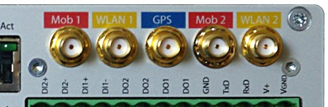
MG102i uses SMA antenna connectors:
Mob 1, Mob 2 for GSM/UMTS/LTE antenna connection (Mob 1 for 1st UMTS module, Mob 2 for LTE as auxiliary second connector or for 2nd UMTS),
GPS for GPS active or passive antenna,
WLAN 1 and WLAN 2 for WiFi Antenna (WLAN 2 as auxiliary).
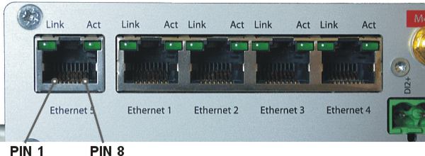
Tab. 4.1: Pin assignment Ethernet interface
| RJ-45 Socket | ETH (Ethernet 10BaseT and 100BaseT) |
|---|---|
| pin | signal |
| 1 | TX+ |
| 2 | TX− |
| 3 | RX+ |
| 6 | RX− |
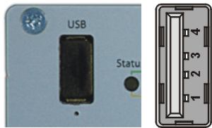
MG102i uses USB 1.1, Host A interface. USB interface is wired as standard:
Screw terminal plug type Stelvio Kontek CPF5/15 or MRT3P/15V01 can be used.
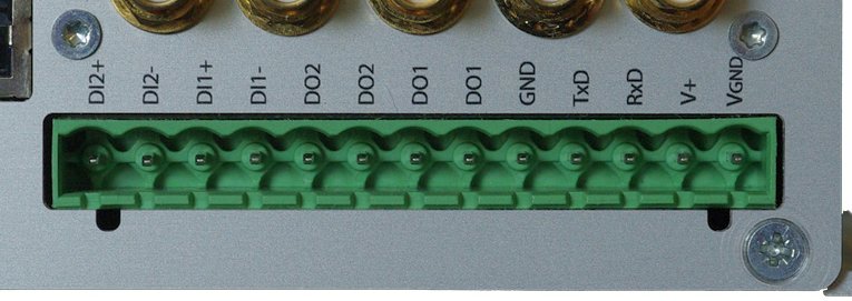
Tab. 4.3: Pin assignment of screw terminal
| pin | pin description | signal |
|---|---|---|
| 1 | VGND | Ground internally connected with casing ground. |
| 2 | V+ (12–48 V=) | Dual power input – not connected with pin 4: 12–48 VDC (–15% +20%) = 10.2–57.6 VDC. |
| 3 | RxD | RS232 – RxD (receiving data) |
| 4 | TxD | RS232 – TxD (transmitting data) |
| 5 | GND | RS232 – GND (ground) |
| 6 | DO1: | Digital output. Dry contact relay. Normally open with MG102i without powering. |
| 7 | ||
| 8 | DO2: | Digital output. Dry contact relay. Normally open with MG102i without powering. See Section 7.2.7, “Digital I/O” for details. |
| 9 | ||
| 10 | DI1− | Digital input 1 See Section 7.2.7, “Digital I/O” |
| 11 | DI1+ | Digital input 1 |
| 12 | DI2− | Digital input 2 |
| 13 | DI2+ | Digital input 2 |
Tab. 4.4: Digital inputs levels
| logical level 0 | 0 to 5.0 VDC |
| logical level 1 | 7.2 to 40 VDC |
| Note: Negative input voltage is not recognised. | |
Tab. 4.5: Digital outputs parameters
| Maximal continuous current | 1 A |
| Maximal switching voltage | 60 VDC, 42 VAC (Vrms) |
| Maximal switching capacity | 60 W |
Tab. 4.6: Voltage Polarity connector misconnection Risks
| pin | pin description | Plug pos. | Plug pos. | Plug pos. | Plug pos. | ||||
|---|---|---|---|---|---|---|---|---|---|
| 1 | VGND | − | OK | + | Nde | − | − | ||
| 2 | V+ (12–48 V=) | + | − | − | Nde | + | OK | ||
| 3 | RxD | − | Dp [1] | + | Dp [1] | + | − | ||
| 4 | TxD | + | − | − | Dp [1] | + | Dp [1] | ||
| 5 | GND | − | Nde | + | Nde | + | − | ||
| 6 | DO1-1 | + | − | − | Nde [2] | + | Nde [2] | ||
| 7 | DO1-2 | − | Nde | + | Nde | + | − | ||
| 8 | DO2-1 | + | − | − | Nde [3] | + | Nde [3] | ||
| 9 | DO2-2 | − | Nde | + | Nde | + | − | ||
| 10 | DI1− | + | − | − | OK [4] | + | Nde [4] | ||
| 11 | DI1+ | − | Nde | + | Nde | + | − | ||
| 12 | DI2− | + | − | − | OK [4] | + | Nde [4] | ||
| 13 | DI2+ | + | − |
Explanatory notes for the table:
OK – Normal operation
DP – Damage possible
Nde
– No damage expected
[2] – If the relay is closed (normally open), the relay is damaged when current > 5 A
[3] – If the relay is closed (normally closed), the relay is damaged when current > 5 A
[4] – If the applied voltage is > 40 V, input circuit damage is likely
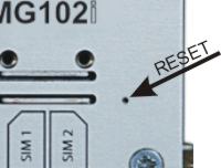
The Reset button is placed close to the SIM holders and it is labeled “Reset”. Use a blunt tool with 1 mm in diameter (e.g. paper clip) to press the button.
Keep it pressed for at least 3 seconds for reboot and at least 10 seconds for a factory reset. The start of the factory reset is confirmed by all LEDs lighting up for one second. The button can be released afterwards.
| Note | |
|---|---|
If the button is being pressed at least 15 seconds until all LED diodes blink red, the recovery procedure is started. The recovery image can be provided on demand and a special procedure utilizing the TFTP transfer from your computer is required. Contact our technical support team for more details. |
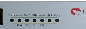
Tab. 4.7: MG102is interfaces and status indicators
| Label | State | Function |
|---|---|---|
| Status | green blinking | Start up, maintenance |
| green on | Ready (upper side banks description) | |
| orange on | Ready (lower side banks description) | |
| orange blinking | Insufficient power supply | |
| Mob1 Mob2 | blinking | Mobile connection is being established |
| on | Mobile connection is up | |
| green | Excellent GSM signal | |
| orange | Medium GSM signal | |
| red | Weak GSM signal | |
| VPN | green on | VPN connection is up |
| green blinking | VPN connection is being established | |
| WLAN | blinking | WLAN connection is being established |
| on | WLAN connection is up | |
| red /orange / green | Weak / Medium / Excellent WLAN signal | |
| GPS | blinking | GPS is turned on, but a valid NMEA stream is not yet available |
| on | GPS is turned on and a valid NMEA stream is available | |
| off | GPS is turned off and a valid NMEA stream is available | |
| Voice | on | A voice call is currently active |
| off | No voice call is active | |
| If lower side banks displayed | ||
| DO1 | on | Closed |
| off | Opened | |
| DO2 | on | Closed |
| off | Opened | |
| DI1 | on | Input set |
| off | Input not set | |
| DI2 | on | Input set |
| off | Input not set | |
WWAN RSSI/RSQ/ASU and LED colour
For Releases newer or equal to 4.0.40.102:
Tab. 4.8: RSSI
| Description | excellent | good | medium | weak | bad | critical | n/a |
| GSM RSSI [dBm] | -59 or more | -61 to -81 | -83 to -91 | -93 to -101 | -103 to -107 | -109 to -111 | -113 or less |
| UMTS RSSI [dBm] | -68 or more | -70 to -84 | -86 to -94 | -96 to -104 | -106 to -110 | -111 to -114 | -116 or less |
| LTE RSRQ [dB] | -49 or more | -50 to -79 | -80 to -89 | -90 to -104 | -105 to -110 | -111 to -117 | -118 or less |
Tab. 4.9: ASU
| Description | excellent | good | medium | weak | bad | critical | n/a |
| GSM | 27 or more | 26 to 16 | 15 to 11 | 10 to 6 | 5 to 3 | 2 to 1 | 0 |
| UMTS | 24 or more | 23 to 16 | 15 to 11 | 10 to 6 | 5 to 3 | 2 to 1 | 0 |
| LTE | 71 or more | 70 to 41 | 40 to 31 | 30 to 16 | 15 to 10 | 9 to 3 | 2 or less |
WLAN Link Quality and LED colour
For Releases newer or equal to 4.0.40.102:
Tab. 4.11: LED Colour
| Colour | green | green | orange | orange | red | red |
| Description | excellent | good | medium | weak | bad | critical |
| WLAN Signal Quality [%] | 90 or more | 89 to 70 | 69 to 50 | 49 to 35 | 34 to 20 | 19 to 0 |
| Note | |
|---|---|
For LED description used in older firmware versions, see the previous manual version at www.racom.eu. |
Tab. 4.12: Technical specifications
| Mobile Interface UMTS |
| |||||||||||||||
| Mobile Interface LTE |
| |||||||||||||||
| Ethernet | 5× Ethernet 10/100 Base-T, Auto MDX, 5× RJ45, bridged or routed | |||||||||||||||
| Serial Interface | 1× 3-wire RS232 on 13-pin screw terminal block | |||||||||||||||
| Digital I/O | 2 digital inputs |
| ||||||||||||||
| 2 digital outputs |
| |||||||||||||||
| USB service interface |
| |||||||||||||||
| Antenna Interfaces | Impedance: | 50 Ω | ||||||||||||||
| Connector: | SMA female | |||||||||||||||
| Power Supply | Input voltage: | 10.2–57.6 VDC (12–48 VDC –15 % / +20 %) | ||||||||||||||
| Power consumption: |
| |||||||||||||||
| Environmental Conditions |
| |||||||||||||||
| Mounting | Flat mounting | |||||||||||||||
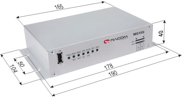
| Dimensions / Weight | 190 W × 104 D × 40 H mm (7.48 × 4.09 × 1.57 in), ca. 610 g (1.35 lb) | |||||||||||||||
| Type Approval | CE, FCC | |||||||||||||||
| Options | |
| 3G or LTE model | |
| GPS SW key | Integrated GPS receiver with
NMEA0183 data stream Supported passive or active GPS antenna, SMA female connector |
| WLAN | Integrated Wi-Fi 802.11 a/b/g/n
client, Wi-Fi 802.11 b/g/n server for max. 128
clients Antenna SMA female, antenna diversity |
| Voice Gateway SW key | VoIP to GSM gateway |
| Mobile IP SW key | Mobile IP VPN tunnel |
| Server License | Expansion SW key for increasing OpenVPN clients from 10 to 25 and other features (see table Server extension). |
| Antennas | Various antennas suitable for your application are available |
| Mounting kit | DIN rail bracket |
Ordering code (Part No’s)
| Trade name: | MG102i |
| Type (according internal module(s)): | MG102i-U, MG102i-L, MG102i-2U |
| Code (according to next HW modules): | e.g. MG102i-UW |
MG102i – XXyy – zzz
XX – module type
| Code | Module | Functionality |
| MG102i-U | UMTS | GPRS/EDGE/UMTS/HSPA |
| MG102i-L | LTE | GPRS/EDGE/UMTS/HSPA+/LTE |
| MG102i-2U | 2×UMTS | GPRS/EDGE/UMTS/HSPA |
yy – HW modules
| empty | – basic model (no HW module) |
| W | – Wifi (Wireless Local Area Network) internal module (Part
No. MG102i-HW-WLAN) |
zzz – SW feature keys
| empty | – empty no SW feature key |
| G | – GPS receiver (Part No. MG102i-SW-GPS) |
| M | – MobileIP VPN tunnel option – see http://en.wikipedia.org/wiki/Mobile_IP for short explanation. (Part No. MG102i-SW-Mobile IP) |
| S | – Server extension |
| V | – Voice Gateway – receive VoIP packets from LAN and change it to calls to the GSM/UMTS network and transform calls incoming from mobile network to the VoIP packets into the LAN. (Part No. MG102i-SW-VoIP) |

Code examples:
MG102i-U = UMTS
MG102i-UW = UMTS + WLAN
MG102i-L(G) = LTE+GPS
MG102i-LW(G)(S) = LTE + WLAN + GPS + Server
extension
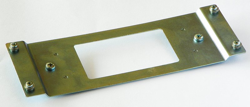

DIN rail bracket
Installation bracket for DIN rail mounting. For usage details see chapter Mounting and chapter Dimensions.