Before you install the device to a mast tube, verify visually that the view in direction of the remote unit is unobstructed. Watch out for these obstacles in particular:
Free Fresnel zones. Signal needs space wider than the diameter of the antenna.
Trees at the lower end of the Fresnel zone. They will be taller in a few years.
Possible building development.
Objects in the close proximity of the antenna such as edges of other antennas, their mounting racks, edges of the roof.
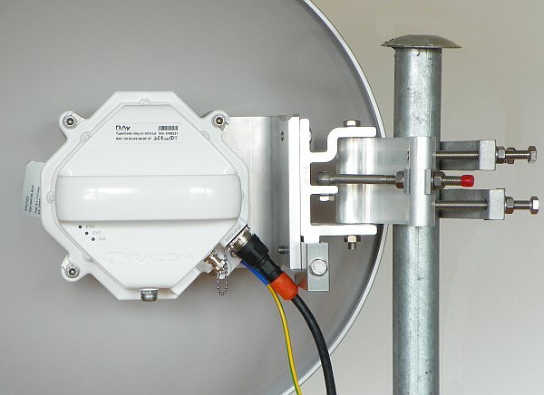
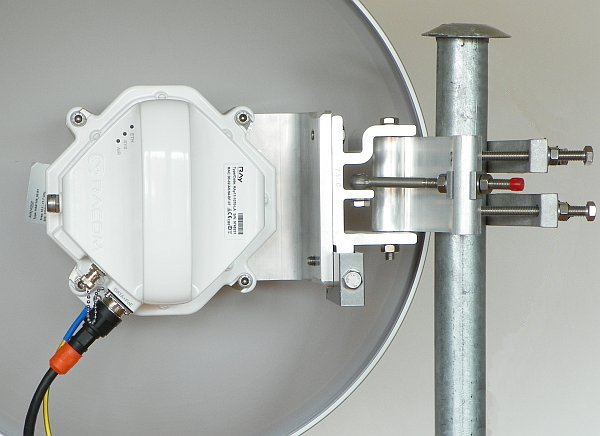
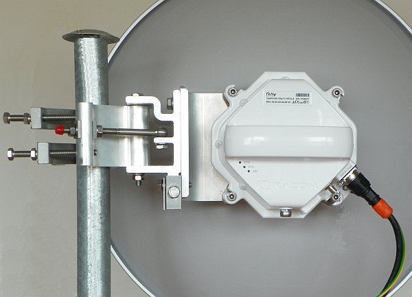
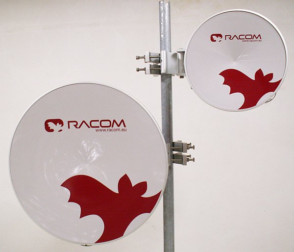
according to the method of mounting on the mast tube
right-side mounting
left-side mounting
according to the method of mounting the FOD unit – antenna polarization
horizontal mounting
vertical mounting
In both cases mount the unit with the connectors facing downwards at an angle.
Changing the mounting method
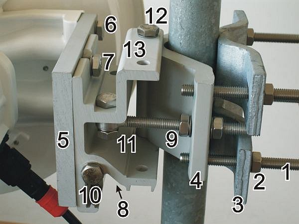
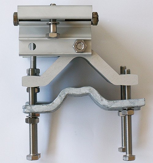
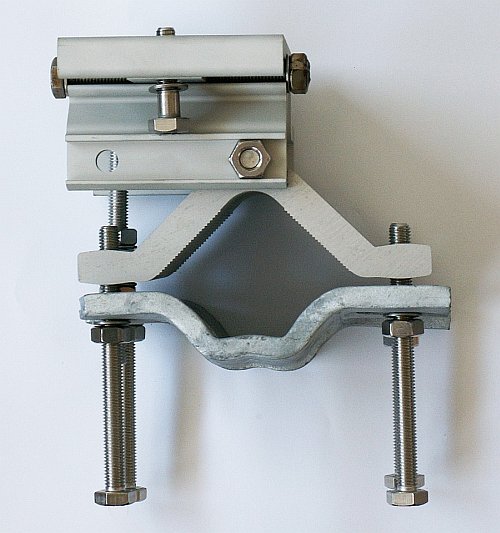
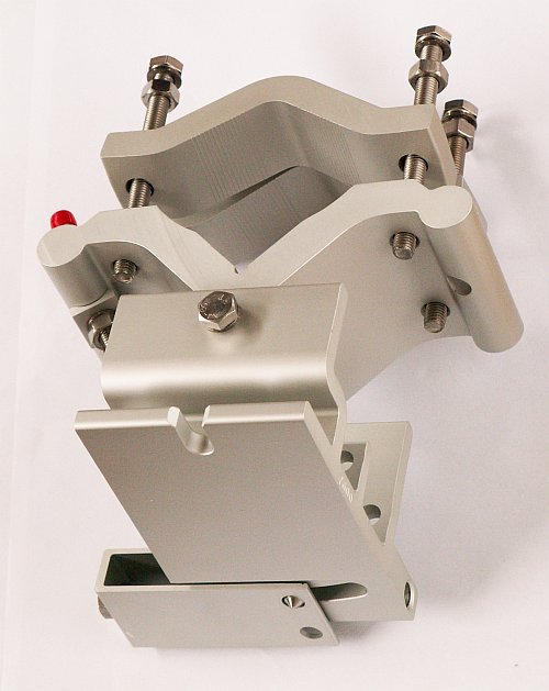
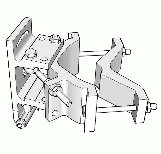
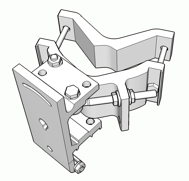
Antenna bracket is supplied as standard partly assembled, and ready for right-side mounting.
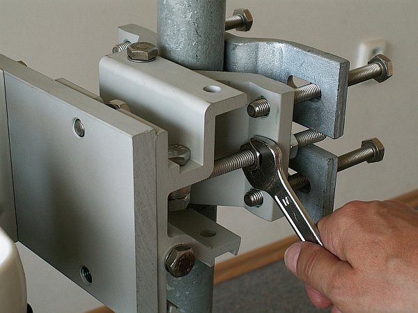
On changing the Jirous antenna bracket for left-side mounting the adjustment bolt (part No. 11) and swivel bolt (part No. 12) need to be unscrewed, then shift the bracket body (part No.13) to the other side of clamp plate (part No. 4), (do not turn upside down) and then insert bolt (part No. 12) into the second hole on the mounting plate holder and through the same hole on the clamp plate and secure in place with the nuts. The adjustment bolt (item No. 11) and nuts (item No. 9) are switched to the other side of the clamp plate (part No. 4). It is also necessary to switch the hanging bolt (part No. 7) on the mounting plate (part No. 5) to the second hole so that after switching sides with the antenna it is on the top again.
On changing the Arkivator type antenna bracket for left-side mounting the adjustment pin (part No. 17) needs to be unscrewed and switched to the other side of the bracket body (part No.3) and clamp plate (part No. 4). It is also necessary to switch the adjustment bolt (part No. 21) and U-plate (part No. 13) to the other side of the bracket body (part No.3). This ensures that there is still good access to the adjustment elements for changing the direction of the antenna when mounted on this opposite side.
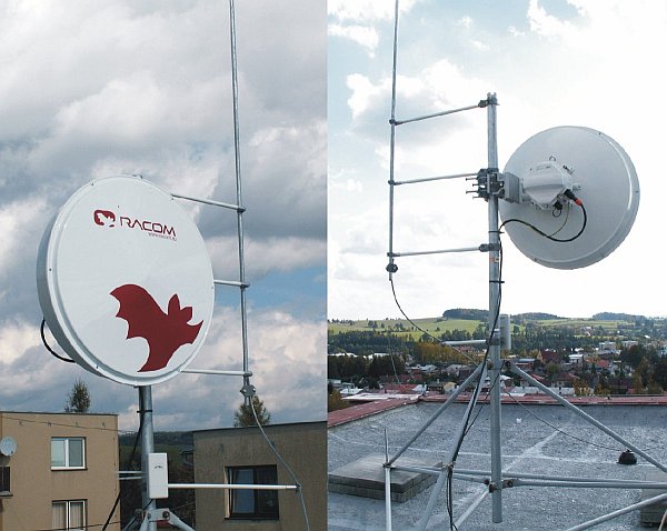
In the case of the antenna when changing the method of mounting from right-side to left-side it is only necessary to change the eye hook on the top and rotate the plastic cover of the antenna. This is not only important from an aesthetic point of view, so that the RACOM logo is not upside down, but also because there is a discharge channel on the lower edge of the dish (except for ø380 mm dishes).
When changing the polarization from horizontal to vertical only the FOD unit needs to be turned through 90° around the central antenna pin by unscrewing the four bolts on the dish using a No. 6 Allen key. (or on the reducing crossplate (part No. 7) for the Arkivator type antenna)
| Important | |
|---|---|
The RAy17 and RAy24 links are equipped with a polarization duplexer and work in both polarizations simultaneously, see Cross polarization. One side of the link must therefore be installed in vertical polarization and the other in the horizontal polarization. |
RAy microwave bridge equipment is generally supplied as several component parts packaged separately in a box.
Two parabolic antennas.
Two brackets for mounting the antenna to the mast.
Two FOD stations, each separate in a box, in a single package.
Other accessories based on the order placed (for more detailed information see chapter Section 3.7, “Accessories”)
When ordering a RAy microwave bridge there is a choice of antennas from two manufacturers to be connected to the RACOM FOD unit.
A No. 17 spanner and a No. 6 Allen key are required for mounting the mechanical parts of the antenna. Spanner No. 17 serves for precisely setting the direction of the antenna. Both spanner and key can be found in the RAy Tool set for installing RAy microwave bridges.
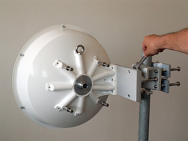
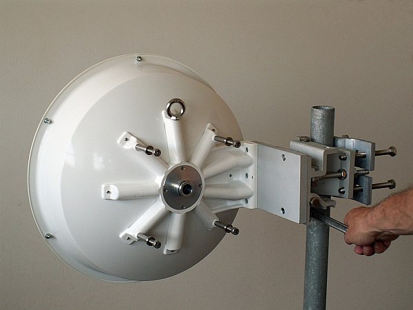
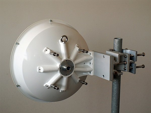
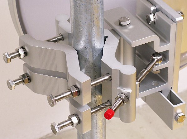
Prepare the antenna bracket based on the diameter of the mast tube. For smaller diameters face the bent part of the saddle plate (part No. 3) inwards. For larger diameters it should face outwards. Screw the bolts (part No. 1) into the clamp plate (part No. 4) so that they protrude approx. 1 cm through the clamp plate. Clamp the saddle plate to the mast by tightening the nuts (part No. 2) on the bolts.
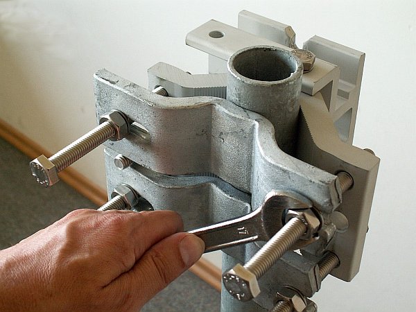
Slide the antenna bracket onto the mast tube and clamp to the mast by tightening the nuts.
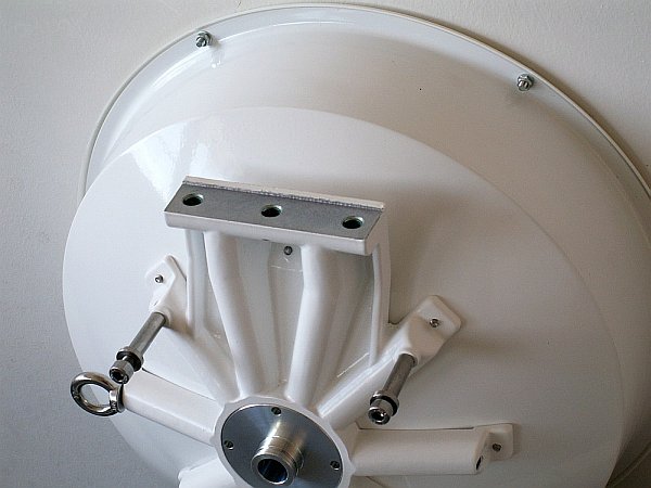
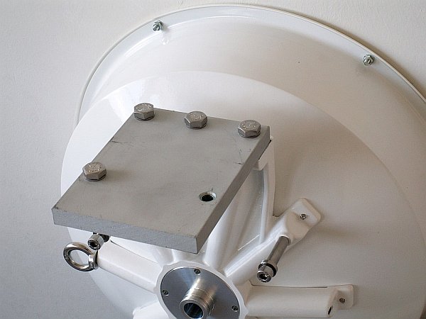
The second part of the bracket – mounting plate (part No. 5), is screwed to the antenna dish with three bolts (part No. 6). Screw the eye hook into the upper threaded hole of the dish to ease handling of the dish during installation. The position of the eye hook on the dish and hanging bolts on the plate change according to the type of installation, see Section 5.2.1, “Mounting methods”.
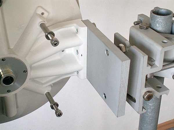
Screw the hanging bolt (part No. 7) into the upper hole of the mounting plate so that the antenna can be hung on the mounting plate holder. Hang the antenna on it and tighten the lower bolt. (part No. 8)
Tighten both bolts to the plate before continuing with installation to prevent any unnecessary movements of the whole equipment. Before precisely adjusting the vertical direction of the antenna upon completing installation it will be necessary to unscrew them again as the lower bolt passes through the adjustment block and the upper one serves as the axis of rotation.
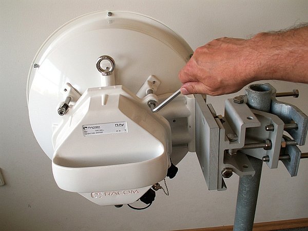
Before installing the FOD unit on the antenna first unscrew the 4 bolts on the back of the antenna enough so that the unit can be slid on to them. Then check whether the “O” ring is correctly fitted on the antenna pin, and make sure it is not damaged and has been lubricated with grease – see Section 5.2.3, “Lubrication and preservation of the antenna pivot”. Then remove the protective plastic cover from the central pin of the antenna and fit the FOD unit to it carefully so as not to damage the “O” ring. Secure it in place with the four bolts. Carefully ensure the correct polarization of the antenna – see Section 5.2.1, “Mounting methods”. Finally tighten the bolts with a No. 6 Allen key.
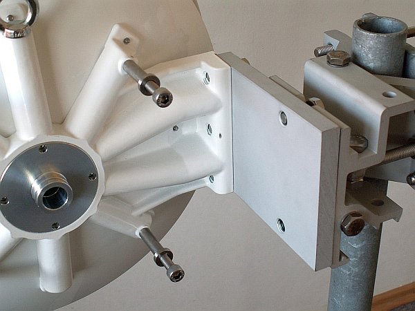
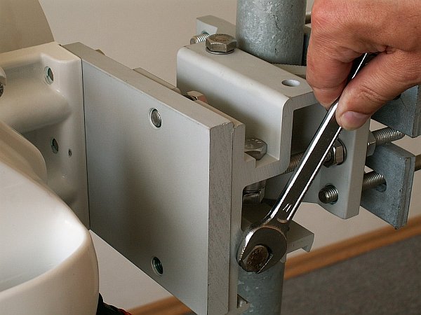
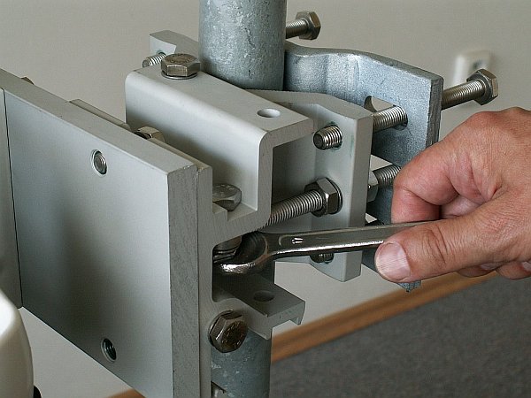
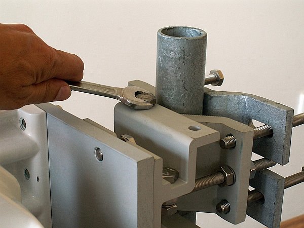
The precise horizontal direction the antenna is pointing in can be adjusted using the bolt with two nuts (part No. 9). Once the direction has been set the antenna is fixed in place by tightening the nuts against the bracket to prevent further movement of the antenna. The vertical direction the antenna is pointing in can be adjusted by turning the fine adjustment bolt (part No. 10) by the bracket mounting plate. After selecting the correct direction the position is secured by tightening the bolt – see point e (part No. 7 and 8). The correct position in both directions is found by monitoring RSS – voltmeter, or with an audible alarm (if equipped) – see Section 5.5.2, “Antennas directing”.
After pointing the antenna in the right direction tighten the bolts on the bracket on the axes of rotation (part No. 11 and 12). Then check again that all other bolts have been sufficiently tightened. We can now proceed to connecting the FOD unit to the user network.
Installation of a RAy microwave bridge with an Arkivator type antenna is very similar to the installation described above, and is clear from the following images. The tools required for installation can be found in the RAy Tool kit for installation of RAy microwave bridges. No. 13, 16 and 17 spanners and No. 4 and 6 Allen keys are required for installation. For an antenna with a nominal diameter of 120 cm a No. 14/24 double open ended spanner, supplied with the antenna.
From 2013 Arkivator antenna is delivered with a slightly different bracket, see Fig. 5.24, “Arkivator antenna bracket, version 2013”. Assembly process is similar.
The antenna bracket (part No. 3 and 4) is supplied assembled as per the following image. The bracket is installed on the mast tube in a similar way to that of the Jirous antenna (point a). The bracket is ready for tube diameters up to 115 mm. The bolts (part No. 6) should be screwed to the clamp plate (part No. 4) in such a way that the end of the bolt protrudes approx. 6-10 mm through the other side of the clamp plate. Saddle plates (part No. 5) are then clamped against the mast tube by tightening nuts (part No. 7).
| Warning | |
|---|---|
Before mounting the adapter (part No. 25) to be removed the green foil from the antenna (part No. 1). This film covers the transport of the center hole in the waveguide. |
After mounting the bracket on the mast tube, bolt the bent plate (part No. 2, for Arkivator 30 and 60) or (part No. 30, for Arkivator 99) to the bracket. The actual antenna (part No. 1) is then bolted to this plate.
A reducing adapter (part No. 25), a reducing crossplate (part No. 21) and sleeves (part No. 22) are used for mounting the FOD unit (part No. 20) on the antenna. During installation do not forget “O” rings (part No. 26 and 27) and to lubricate the “O” ring (part No. 27), see Section 5.2.3, “Lubrication and preservation of the antenna pivot”.
Bolt (part No. 14) serves for accurately setting the vertical direction of the antenna. When setting the direction release bolt (part No. 12 and 13), and then tighten it again once you have the correct position. The nuts on bolt (part No. 10) serves for setting the horizontal direction. Once the direction is set these nuts (part No. 11), pivot bolt (part No. 9) in the hanging eye of bolt and two pivot bolts (part No. 8) where the tilt bracket is need to be tightened.
Before fitting the FOD unit bush onto the antenna pivot ensure that the “O” ring (part No. 1) is in the correct position. It is also essential to prevent moisture getting in between these two parts. This moisture could cause oxidation which would complicate disassembly of this mechanical coupling in the future. For this reason we need to treat these surfaces with the lubricant grease which is supplied in the box marked RAy bridge accessories. If you use a different grease for lubrication then it should be a Teflon grease or a silicon lubricant grease.
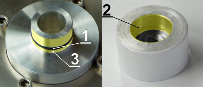
Grease the internal area of the bush on the FOD unit (2) and the “O” ring (1) with a thin even layer that allows the pin to slide easily into the bush without damaging the “O” ring. Grease the area beyond the “O” ring on the antenna pin (3) with a thicker layer so that it fills the gap caused by the play between the pin and the bush (max. 0.1 mm/ø) thus preventing moisture getting in. Installation should be carried out according to the antenna installation description – see point f of this description.
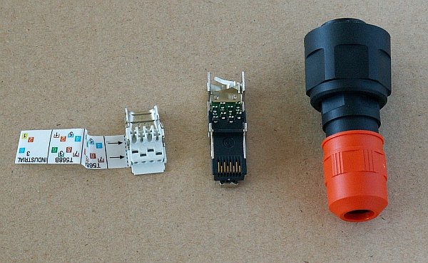
The FOD communication unit is connected to the user network by an Ethernet cable via interfaces GbE, IEEE802.3ac 1000BASE-T. As standard, RACOM recommends using an S/FTP CAT 7 cable and two RJ45 connectors for outdoor installations. One for the internal (IE-PS-RJ45-FH-BK) and the second for the external (plastic IE-PS-V01P-RJ45-FH or metallic IE-PS-V01M-RJ45-FH) end of the cable.
Based on the PoE standard the station is powered over the Ethernet cable.
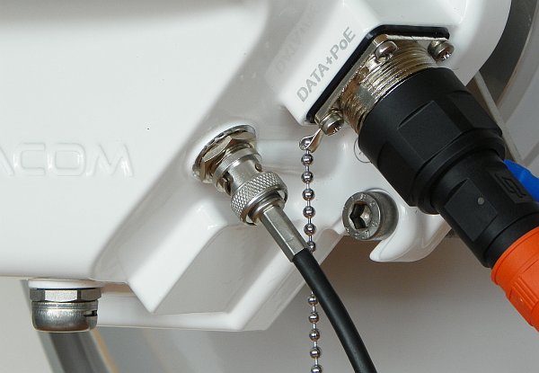
If the station is equipped with two connectors, the right one carries user data, and the left connector is to be used for servicing.
The middle BNC type connector serves for connecting a voltmeter for precisely setting direction.
| Important | |
|---|---|
Before connecting the FOD communication unit to the supply (to the user network) the FOD unit must be grounded according to Section 5.4, “Grounding”. |
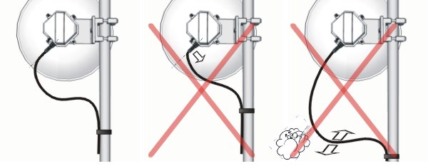
It is necessary to install the antenna lead so that there is no excessive mechanical stress applied on the Ethernet connector.
We recommend using an S/FTP 4×(2×23AWG) Cat.7 + 2×(2×24 AWG) cable for connecting the FOD unit, as it is designed for external use. The cable contains two additional twisted pairs, 2x(2×24 AWG), which are not used. The following images show the internal cable without these additional pairs.
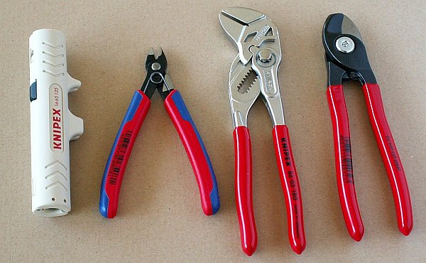
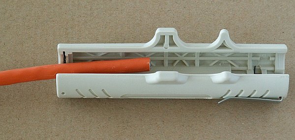
Use the tools from the RAy Tool set for fitting connectors. See Section 3.7, “Accessories”.
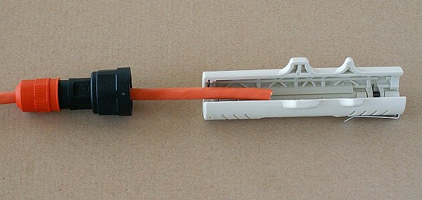
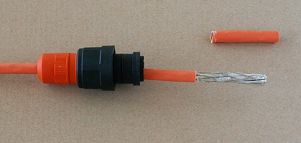
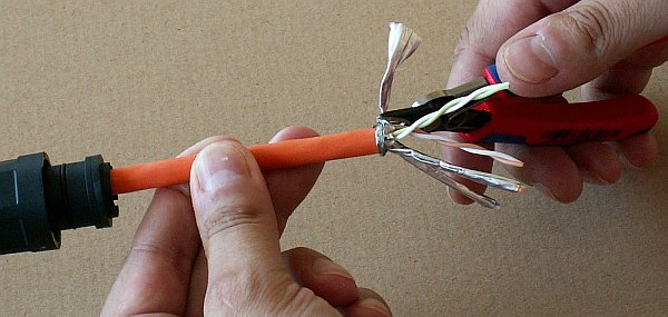
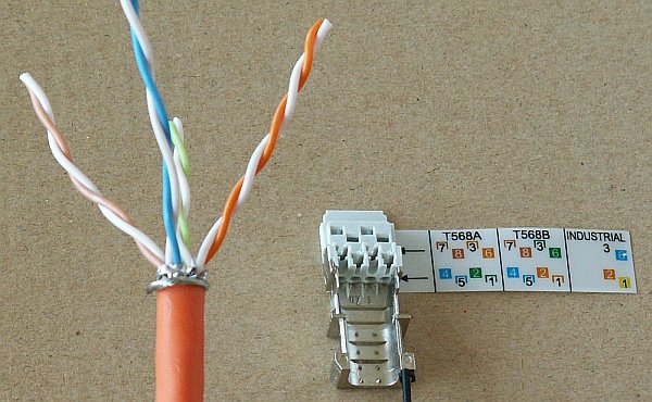
Undo the nut on the connector cover and push it on to the cable. Then trim at least 20 mm of insulation from the end of the cable.
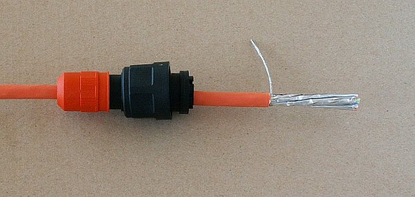
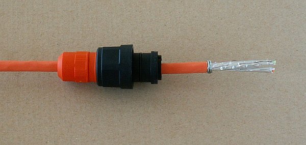
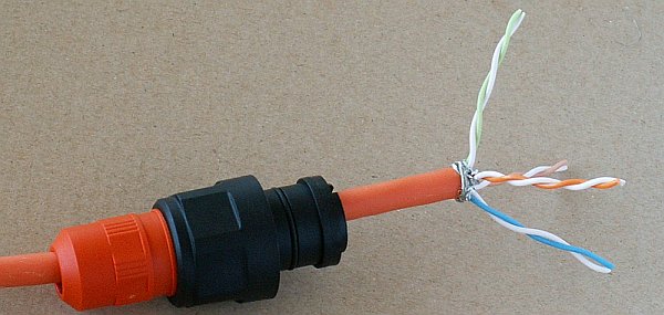
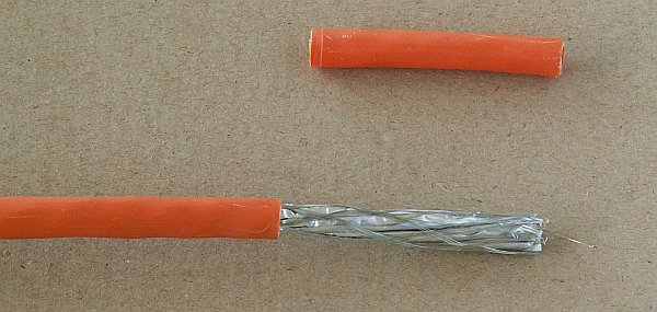
Twist the braid forming the cable shielding together and wrap around the cable so that 2-3 loops are next to each other at the end of the insulation.
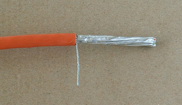
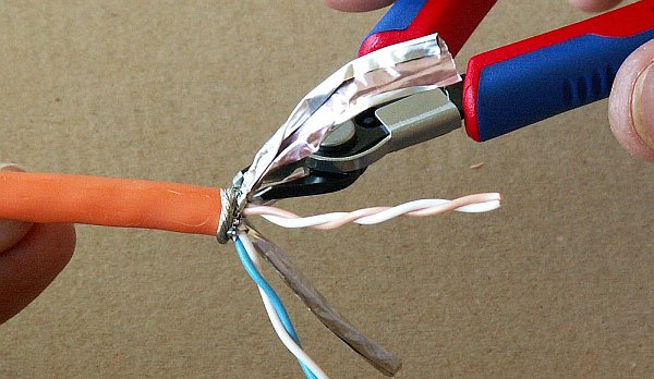
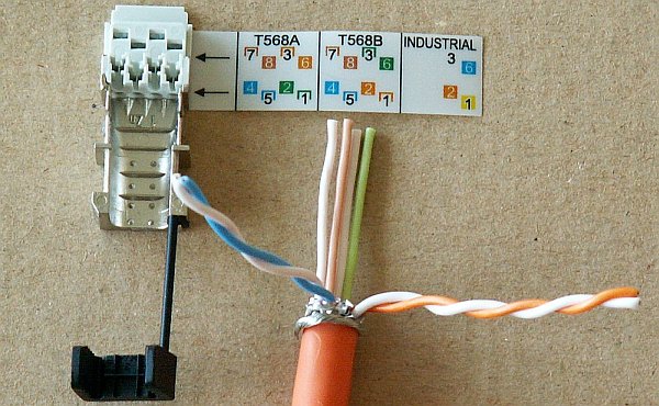
Separate individual pairs of conductors, remove the aluminium shielding from them, cut it off, and separate individual conductors. Cut off the two additional twisted pairs from the thinner wire in the middle (not seen on these images).
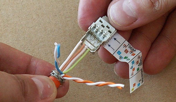
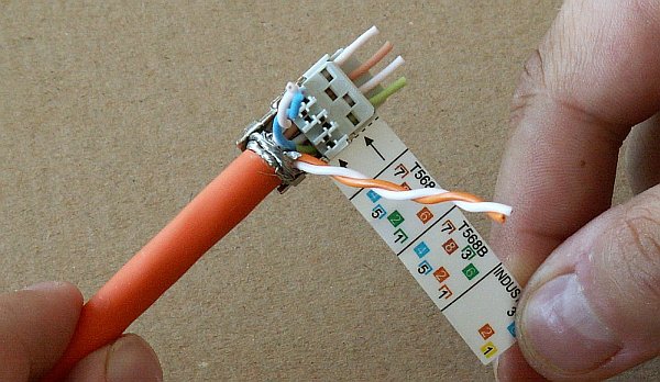
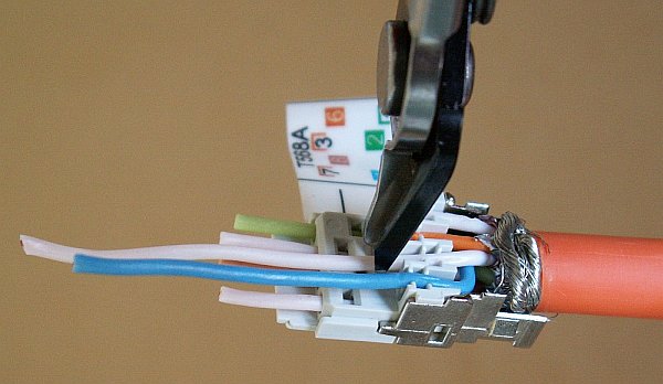
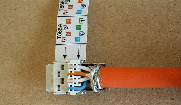
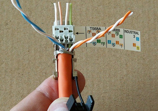
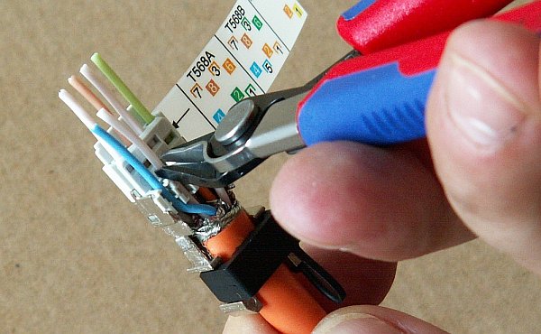
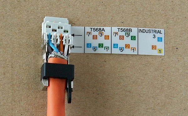
Push the lower layer of conductors into the openings as per the pinout sticker (T568B) attached to the connector. Take care not to confuse white conductors from individual pairs.
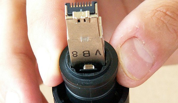
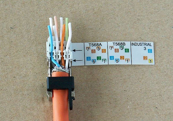
Then from above push the upper conductors into the connector according to the pinout sticker and trim them. The cable must be pushed in far enough so that the braided shielding is inside the metal part of the connector.
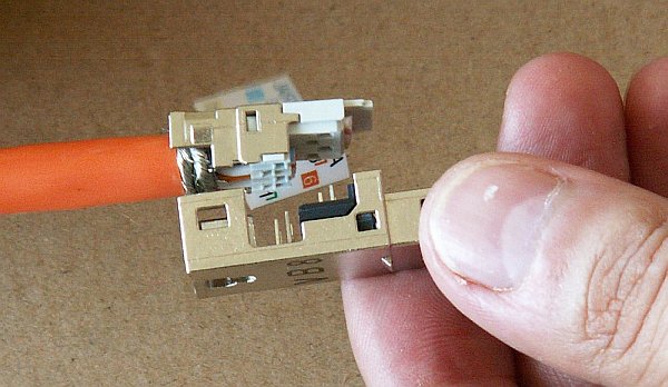
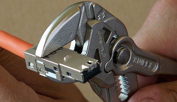
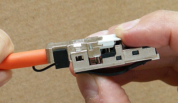
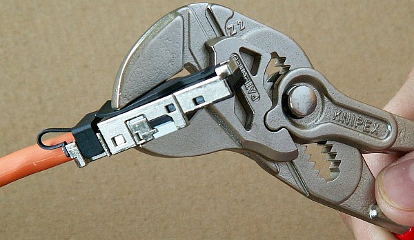
Remove the pinout sticker and fit the complementary half of the connector. Squeeze the parts together until the locks snap into place. Use the pair of pliers with parallel jaws from the RAy Tool set for this. Standard pliers would damage the connector.
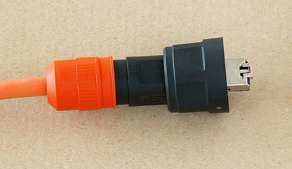
Then slide the protective cover onto the connector. It must fit into the grooves after snapping into place. Finally tighten the nut on the cover to seal the point where the cable enters the connector.
Use the same tools as for fitting the external connector. The internal connector does not have a cover.
Trim at least 20 mm of insulation from the end of the cable.
Twist the braid forming the cable shielding together and wrap around the cable so that 2-3 loops are next to each other at the end of the insulation. Separate individual pairs of conductors, remove the aluminium shielding from them, cut it off, and separate individual conductors. Cut off the two additional twisted pairs from the thinner wire in the middle (not seen on these images).
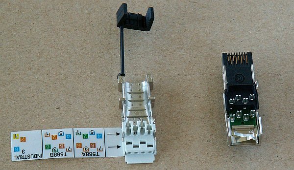
Prepare individual pairs according to the pinout sticker attached to the connector (T568B) and unwind the two pairs for the bottom part of the connector. Take care not to confuse white conductors from individual pairs.
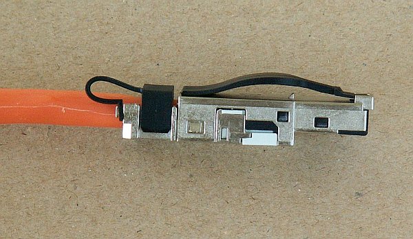
First insert the lower row of conductors from the back. Then unwind the others and insert them into the holes for the upper row of conductors, as per the pinout sticker. Ensure that the wrapped around shielding braid is inserted sufficiently to create a good contact with the second part of the connector fitted with sprung contacts. Snap the plastic clamp onto the cable. Squeeze it together tight enough so that it doesn’t allow movement of the cable.
Trim the overhanging conductors.
Remove the pinout sticker from the connector and slide on the mate. Clamp the whole connector together until the locks snap into place. Use a pair of pliers with flat heads from the RAy Tool set. Ordinary pliers could damage the connector.
The lightning and overvoltage protection system example, designed in accordance with regulation CSN EN 62305.
Where possible the antenna should be located in an LPZ 0B protection zone with the use of a local or artificial air termination device for protection against direct lightning strikes.
When meeting conditions for ensuring electrical insulation (distance from the lightning conductor) in accordance with article 6.3, it is not recommended to ground the load-bearing structure and antenna to the external air termination network. Ground should be connected to the protective system of the internal LV wiring or grounded internal structures using a CYA 6 mm2 bonding conductor , see Fig. 5.61, “Grounding installation 1”
If it is not possible to set up conditions of electrical insulation in accordance with article 6.3 we recommend connecting the load-bearing structure at roof level to the external air termination network via an 8mm diameter FeZn conductor and shielding the data cable before entry to the building with a grounding kit and CYA 6 mm2 conductor to the bonding bus, and if not already set up then also to the external air termination network, see Fig. 5.62, “Grounding installation 2”
If there is not an external LPS on the building we recommend routing lightning current through an 8mm FeZn conductor to a common grounding system, or to a separate grounding electrode with a ground resistance up to 10 Ω.
For limiting the overvoltage transferred over the data cable and into the building we recommend fitting surge protection at the interface between zones LPZ 0 and LPZ 1 connected via a CYA 4 mm2 conductor to the same grounding point as the antenna or the antenna mast.
We recommend protecting the PoE power supply from overvoltage on the LV side with suitable class D surge protection.
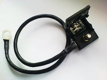
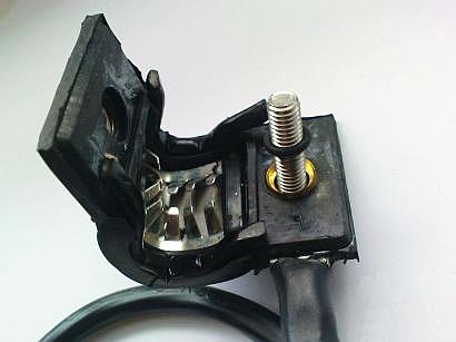
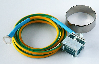
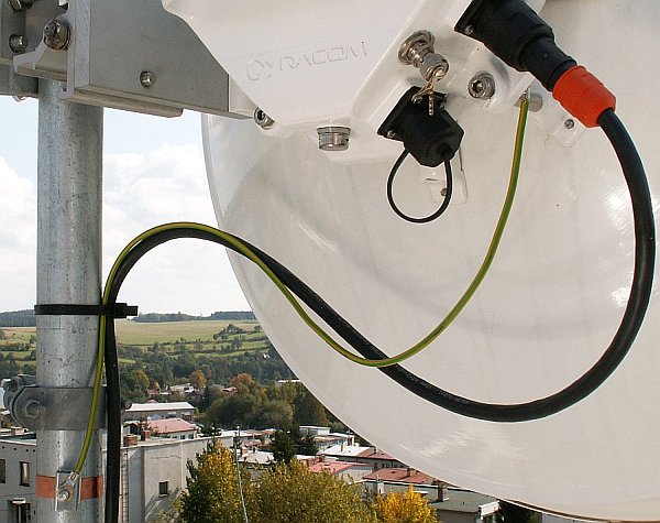
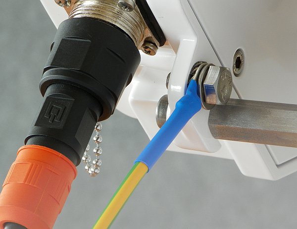
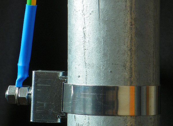
The RAy unit is grounded to the flange by the Ethernet connector using an M6 screw. An insulated copper cable with a minimum diameter of 6 mm2 terminated with a terminal lug is used as a protective conductor. The conductor should have a green/yellow sheath across its whole length. For grounding a RAy grounding kit can be ordered as an accessory (see Section 3.7, “Accessories”) containing a grounding terminal ZSA16, 40 cm grounding strip 15 mm wide, and 100 cm of cable with grounding lugs. For instructions on installing terminals see the datasheet RAy grounding kit. A qualified person must install the antenna.
Racom supplies surge protection for installation on Ethernet cables entering buildings. For more details see Surge protection.
Additional safety recommendations
Only qualified personnel with authorisation to work at heights are entitled to install antennas on masts, roofs and walls of buildings.
Do not install the antenna in the vicinity of electrical wiring. The antenna and bracket should not come into contact with electrical wiring at any time.
The antenna and cables are electrical conductors. During installation electrostatic charges may build up which may lead to injury. During installation or repair work to parts of the antenna lead open metal parts must be temporarily grounded.
The antenna and antenna cable must be grounded at all times. See Section 5.4, “Grounding”.
Do not mount the antenna in windy or rainy conditions or during a storm, or if the area is covered with snow or ice.
Do not touch the antenna, antenna brackets or conductors during a storm.
Connect a power supply to the installed FOD unit and connect the configuration PC. Use an internet browser (such as Mozilla Firefox) to enter the configuration menu.
This chapter is particularly true for installation of links working in free bands, where the user has no secured frequency.
Analyse the level of noise in the individual channels using the spectrum analyzer under Tools – Graphics – Frequency analyzer. If necessary adjust the choice of working channel on the basis of the results.
While doing so respect the rule that in one location all units emit signal in the Upper part of the range and receive it in the Lower part of the range, or the other way round. A transmitter must not be installed in the part of the spectrum where other units function as receivers.
If it is possible, use narrow channel, low modulation and high power for the first antenna directing. Working on both ends of the link simultaneously is favourable. Connect voltmeter to the BNC connector and observe RSS changes in 2 V DC range. Stronger signal corresponds to lower voltage. Alternate units on both sides and slowly adjust the antenna vertically and horizontally to find the position with the strongest reception. At the same time look for the main signal maximums. To differentiate between the main and the side maximums refer to Main and side lobes paragraph.
RSS measurement
For correctly setting the bridge and positioning it in the right
direction it is advisable to connect a PC and use the diagnostic
capabilities of the RAy station. In uncomplicated cases it is enough
to connect a voltmeter via a BNC connector and adjust to the lowest
indicated voltage. Voltage is calibrated according to signal strength.
E.g.:
RSS -65 dBm corresponds to voltage
0.65 V,
RSS -80 dBm corresponds to voltage
0.80 V etc.
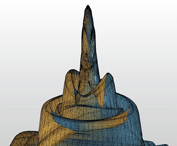
Main and side lobes
Both antennas should be oriented towards each other using the peaks of radiation diagram. Adjust the antenna alternately in the horizontal and vertical axes and monitor the resulting signal strength. Use the calculation of the expected RSS with the precision of several dBm as guidance. Side lobes transmit signal ca 20 dBm weaker, see the Microwave link Calculation.
The resulting RSS helps distinguish between the states A-A and C-C which appear similar. It also helps in situations where simple search for a maximum doesn’t work as shown in the illustration “incorrect adjustment”.
Real radiation diagrams are more complex, especially in that they run differently in horizontal and vertical axes. The basic steps for determining the main radiation lobe however stay valid. For example:
Basic parameters of the link are shown in the menu Status – Brief, its quality is characterized by RSS and SNR. Values on Status screens can be refreshed manually by pressing the Refresh button or in real time with a period of several seconds after activating the Start button. Press the Stop button to terminate the periodic refresh of values.
The RSS, SNR and BER values can also be viewed on the screen Tools – Graphics – Bar indicators. After pressing the Start button, values will be refreshed with a period of one second.
After installation, it is good to reset the statistics using the Clear stats button in menu Status – Detailed. This allows easier diagnostics of the link’s reliability over time.
After both antennas have been directed, setup operation parameters for the link. In case of links operating in the free band, setup the parameters based on survey results from the tool Tools – Graphics – Frequency analyser. In case of links operating in licensed band, setup the parameters based on assigned license:
Bandwidth
Channel Selection (TX / RX channel)
Modulation (TX modulation) – ACM is recommended. When selecting fixed modulation it is necessary to account for the fade margin. If fixed modulation is setup close to a possible maximum, then a deterioration in RSS could endanger the link both for data transfer as well as service access.
Transmit power (RF power), or ATPC
Verify and record IP addresses
Define access channels – https / telnet / ssh / ssh with password
Restart both units by interrupting their power supply and verify the status of the link. This verifies that all parameters have been stored correctly in the memory.
Select Tools – Maintenance – Backup – Settings – Backup – Download and save the configuration to backup file “cnf_backup.tgz”.
This completes the installation. Further configuration can be performed remotely.