https//www.racom.eu/eng/products/m/ray17/index.html
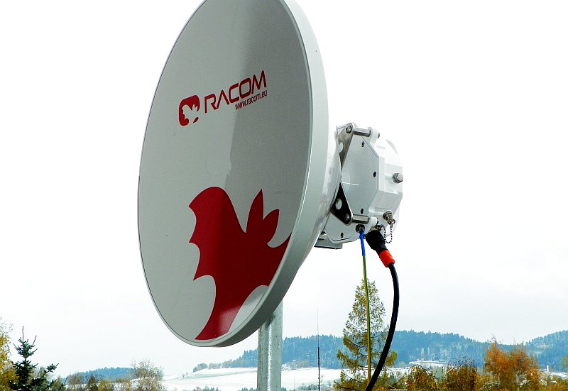
Table of Contents
- Important Notice
- Quick Start Guide
- List of documentation
- 1. RAy – Microwave Link
- 2. Implementation Notes
- 3. Product
- 4. Step-by-step Guide
- 5. Installation
- 6. Configuration
- 7. Command Line Interface
- 8. Troubleshooting
- 9. Technical parameters
- 10. Safety, environment, licensing
- A. Antenna dimensions
- B. Rain Zone Map
- C. IP address in the PC
- D. Linux key conversion
- E. Https certificate
- Index
- F. Revision History
List of Figures
- 1. Link Configuration
- 2.1. Rain zone map, based on Rec.ITU-R PN.837-1
- 2.2. Attenuation for 10 GHz, polarization H, V
- 2.3. Attenuation for 11 GHz, polarization H, V
- 2.4. Attenuation for 17 GHz, polarization H, V
- 2.5. Attenuation for 24 GHz, polarization H, V
- 2.6. Fresnel zone
- 2.7. Design flowchart
- 3.1. RAy – Microwave link
- 3.2. RAy Microwave link – antenna and FOD unit
- 3.3. RAy Microwave link – connectors
- 3.4. Status LEDs
- 4.1. Link Configuration
- 4.2. Configuration Menu Settings – General
- 4.3. Configuration menu Settings – Service access – Services
- 4.4. Configuration menu Settings – Service access – Services
- 5.1. Left-side mounting – horizontal polarization of receiving
- 5.2. Left-side mounting – vertical RX polarization
- 5.3. Right-side mounting – horizontal RX polarization
- 5.4. Close up image of the mounted bracket showing numbered parts
- 5.5. Position of the saddle plate for ø 40–80 mm
- 5.6. Position of the saddle plate for ø 65–115 mm
- 5.7. Attaching the bracket to the mast tube
- 5.8. Dish without mounting plate
- 5.9. Dish with mounting plate
- 5.10. Hanging the bolt on the holder
- 5.11. Correct position of the mounting plate
- 5.12. Tightening the upper bolt to the mounting plate
- 5.13. Tightening the lower bolt to the mounting plate
- 5.14. Dish before installing the FOD unit
- 5.15. Tightening bolts on the FOD unit
- 5.16. Horizontal adjustment of the antenna direction
- 5.17. Vertical adjustment of the antenna direction
- 5.18. Tightening the axis at the fine adjustment bolt
- 5.19. Tightening the axis at the bracket
- 5.20. Installation diagram for the Arkivator antenna, 30 and 60 cm, version 2012
- 5.21. Installation diagram for the Arkivator antenna, 99 cm, version 2012
- 5.22. Arkivator antenna bracket (2012)
- 5.23. Bracket on the mast, version 2012
- 5.24. Arkivator antenna bracket, version 2013
- 5.25. Arkivator antenna bracket (2013)
- 5.26. 30 and 60 cm diameter Arkivator antenna
- 5.27. Installation diagram for the Arkivator antenna, 120 cm
- 5.28. Grease points on the antenna pivot and FOD unit bush
- 5.29. Connecting the FOD communication unit
- 5.30. Example of a correct lead installation.
- 5.31. Tools for fitting connectors
- 5.32. IE-PI-RJ45-FH connector before fitting
- 5.33. Tool for removing insulation
- 5.34. Insulation removed
- 5.35. Twisted shielding
- 5.36. Shielding wrapped around the cable
- 5.37. Trimming shielding
- 5.38. Separated pairs of conductors
- 5.39. Pushing the lower pairs into the connector
- 5.40. Lower pairs pushed in
- 5.41. Cutting off of the upper conductors
- 5.42. All conductors in the connector
- 5.43. Fitting the complementary half of the connector
- 5.44. Squeezing the connector until the locks snap into place
- 5.45. Sliding the cover onto the connector
- 5.46. Finished IE-PI-RJ45-FH connector
- 5.47. IE-PS-RJ45-FH-BK connectorbefore fitting
- 5.48. Finished connector IE-PS-RJ45-FH-BK
- 5.49. Removing insulation
- 5.50. Removed insulation
- 5.51. Twisted shielding
- 5.52. Removing aluminium conductor shielding
- 5.53. Separated pairs of conductors
- 5.54. Lower two pairs ready for inserting
- 5.55. Lower pairs pushed in
- 5.56. All conductors in the connector
- 5.57. Trimming conductors
- 5.58. Inserted and trimmed conductors
- 5.59. Fitting the mate to the internal connector
- 5.60. Clamping the internal connector together with pliers
- 5.61. Grounding installation 1
- 5.62. Grounding installation 2
- 5.63. Grounding kit for S/FTP 4+2 cable
- 5.64. Grounding kit detail
- 5.65. RAy grounding kit
- 5.66. Grounding the FOD unit
- 5.67. Protective conductor at the FOD unit
- 5.68. Protective conductor at the mast on a ZSA16 terminal
- 5.69. Separated lightning conductor
- 5.70. Connecting a voltmeter to the BNC connector.
- 5.71. Radiation diagrams
- 5.72. Radiation diagram – incorrect adjustment
- 5.73. 3D example of more complicated Radiation Pattern
- 6.1. Info Refresh
- 6.2. Login
- 6.3. Status bar 1
- 6.4. Status bar 2
- 6.5. Menu Status
- 6.6. Menu Settings – General
- 6.7. Configuration menu Settings – Radio
- 6.8. Configuration menu Settings – Ethernet
- 6.9. Configuration menu Settings – QoS
- 6.10. Configuration menu Settings – QoS – 802.1p
- 6.11. Configuration menu Settings – QoS – DSCP
- 6.12. Configuration menu Settings – QoS – TCP/UDP ports
- 6.13. Configuration menu Settings – QoS – Queue management
- 6.14. Configuration menu Settings – Service access – Services
- 6.15. Configuration menu Settings – Service access – Users
- 6.16. Configuration menu Settings – Alarm limits
- 6.17. Configuration menu Diagnostics – Graphs
- 6.18. Configuration menu Diagnostics – Graphs – Viewer
- 6.19. Configuration menu Diagnostigs – Graphs – Data
- 6.20. Configuration menu Diagnostics – Logs
- 6.21. Configuration menu Tools – Ping
- 6.22. Configuration menu Tools – Graphics – Bar indicators
- 6.23. Configuration menu Tools – Graphics – RX constellation diagram
- 6.24. Configuration menu Tools – Graphics – Frequency analyser
- 6.25. Configuration menu Tools – Maintenance – Restart
- 6.26. Configuration menu Tools – Maintenance – Backup
- 6.27. Configuration menu Tools – Maintenance – Firmware
- 6.28. Configuration menu Tools – Maintenance – Firmware
- 6.29. Configuration menu Tools – Maintenance – Radio adaptation
- 6.30. Menu Help
- 6.31. Parameter help
- 6.32. Configuration menu help
- 7.1. CLI menu
- 10.1. Declaration of Conformity for RAy11
- 10.2. Declaration of Conformity for RAy17
- 10.3. Declaration of Conformity for RAy24
- 10.4. Country of Origin Declaration
- A.1. Jirous antenna 68
- A.2. Jirous antenna 90