The RAy microwave links are designed for data transmissions in both licensed and unlicensed ISM bands. They work as a point-to-point link in full duplex regime with transfer speed up to 360 Mbps. Bandwidth is selectable from 1.75 up to 56 MHz. Modulation can be fixed or adaptive and can be adjusted from QPSK to 256QAM.
The link is formed by two FOD (Full Outdoor) stations. In the case of links operating in the ISM bands (RAy17, RAy24), both stations have identical hardware. In the case of links operating in the licensed bands, one unit is transmitting in the Lower and receiving in the Upper part of the band. The other unit is operating vice versa.
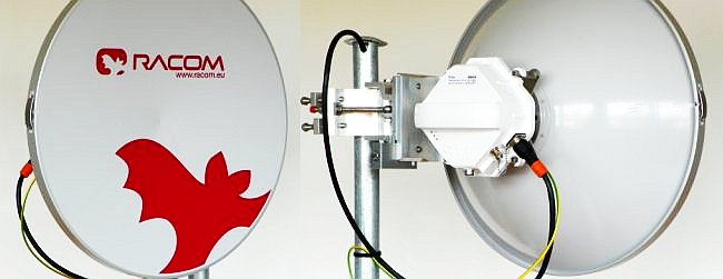
RAy links are used with external parabolic antennas. Parabolic antennas from different producers are available.
Cross polarization – valid only for links operating in the ISM bands (RAy17, RAy24):
One side of the link uses one polarization for transmission (e.g. horizontal) and the opposite polarity for receiving (e.g. vertical). The other side of the link is turned by 90°. It therefore transmits and receives using opposite polarizations with respect to the other side.
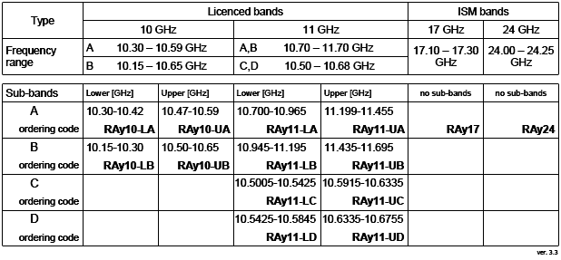
| RAy11-LA | frequency 10.70 – 10.96 GHz, unit L | |
| RAy11-LB | frequency 10.96 – 11.20 GHz, unit L | |
| RAy11-LC | frequency 10.5005 – 10.5425 GHz, unit L | |
| RAy11-LD | frequency 10.5425 – 10.5845 GHz, unit L | |
| RAy11-UA | frequency 11.20 – 11.45 GHz, unit U | |
| RAy11-UB | frequency 11.45 – 11.70 GHz, unit U | |
| RAy11-UC | frequency 10.5915 – 10.6335 GHz, unit U | |
| RAy11-UD | frequency 10.6335 – 10.6755 GHz, unit U |
| RAy17 | universal unit for 17.10 – 17.30 GHz band | |
| RAy24 | universal unit for 24.00 – 24.25 GHz band |
Every model can be supplied in two different versions:
with one metal Ethernet port, e.g. RAy17
with two metal Ethernet ports, e.g. RAy17-2
For details see Section 3.6, “Ordering codes”
A detailed table of frequencies can be found in Chapter 9, Technical parameters.
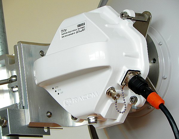
The antenna is attached to the mast using a holder adjustable in two planes. The RAy unit is then mounted on the antenna. There are two possible mounting positions – for horizontal and vertical polarization. Installation and adjustment of the holder is described in Chapter Antenna mounting.
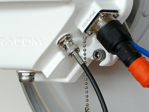
LAN connection is possible using one or two connectors:
The RAyXX version uses a single connector for user data, service access and PoE
The RAyXX-2 version uses two connectors, one for user data and PoE power supply and one for service access. For assembly of connectors see chapter Connectors.
The third BNC connector serves for connecting voltmeter for RSS indication during the antenna adjustment process.
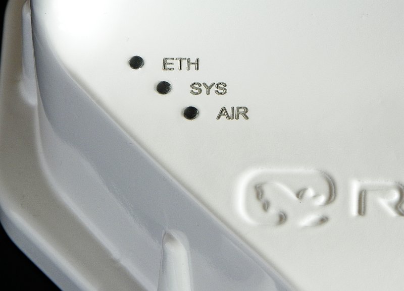
Tab. 3.1: Meaning of LED status indicators
| Diode | Colour | Function |
|---|---|---|
| ETH | Green | User port Flashing slowly: Auto Negotiation in progress Flashing rapidly: Link Activity 10/100/1000 Permanently lit: Link 10/100/1000 |
| Yellow | Management port Flashing: Link Activity 10/100 Permanently lit: Link 10/100 | |
| SYS | Green | Permanently lit: System OK Flashing rapidly: Booting Flashing slowly: Operating system in service mode |
| Red | Permanently lit: Station is performing
defaults. Firmware writing in progress. DO NOT POWER OFF. Flashing slowly: Serious system error. | |
| AIR | Green | Permanently lit: AIR link OK |
| Red | Permanently lit: AIR LOSS, loss of connectivity |
Basic technical parameters are stated in Chapter 9, Technical parameters
Communication unit ODU
| Outer size |
|
| Weight |
|
Diameters of supplied antennas
RAy units are ready for direct mounting to Jirous Class 2 antennas.
Individual datasheets are accessible
here.
10, 11 GHz:
38 cm, 29.0 dBi
65 cm, 35.5 dBi
90 cm, 37.5 dBi
120 cm, 41.0 dBi
17 GHz:
40 cm, 34.8 dBi
68 cm, 38.6 dBi
90 cm, 41.0 dBi
120 cm, 44.6 dBi
24 GHz:
40 cm, 36.8 dBi
68 cm, 41.7 dBi
90 cm, 44.0 dBi
120 cm, 46.6 dBi
Andrew (Class 2 or 3) or Arkivator antennas are also possible to be used with antenna mounting kit. Flexible waveguide is a general-purpose option for any antenna usage.
Name plate
The plate contains name, bar code record, CE label, etc.:
Type – RAy product line identification
Code – detailed identification of the station type (see annex for details Section 3.6, “Ordering codes”)
S/N – serial number, link contains stations with two different numbers
MAC – HW address of user ethernet port
The proper pair of Lower and Upper units should be selected when ordering the microwave link. This is not true for ISM bands units (RAy17, RAy24). In such a case the same unit is used for both sides of the link.
Note – The Lower and Upper unit has to be selected from the same sub-band (i.e. from the same row of the table).
The RAy10 ordering codes are stated here for clarity. The RAy10 User manual can be found here.
In case of the two-port units, the “-2” label shall be connected to the end of the ordering code. Example:
RAy11-LA-2
RAy17-2
The Feature keys ordering code consists of three parts:
XXX-YYY-ZZZ
XXX
– Product type, e.g. “RAy11”.
YYY
– Feature key type.
The
“SW” key is available now. This key unlocks the User speed to given
value.
ZZZ – Feature
key value. In case of User speed it states Mbps. Example:
RAy11-SW-100 … RAy11 user data speed max. 100 Mbps.
RAy17-SW-360 … RAy17 user data speed max. 360 Mbps.
The microwave bridge comes supplied as standard with:
two FOD units
two antenna dishes with brackets for mounting on a mast – based on the user requirements and specifications
tub of NOVATO silicon lubricant (mixture of silicon grease, PTFE and other additives) for lubricating the antenna pin. (see Section 5.2.3, “Lubrication and preservation of the antenna pivot”)
Microwave bridge accessories need to be ordered separately, for further details please see www.racom.eu
| RACOM-PART-NUMBER | Short description | |
| Antenna Jirous | ||
| ANT-JRMA-380-10/11R | Antenna parabolic 0.38 m 10-11GHz with holder 28.0-29.0 dBi Class 2 | |
| ANT-JRMA-650-10/11R | Antenna parabolic 0.65 m 10-11GHz with holder 34.1-35.5 dBi Class 2 | |
| ANT-JRMB-900-10/11R | Antenna parabolic 0.9 m 10-11GHz with holder 37.0-37.5 dBi Class 2 | |
| ANT-JRMB-1200-10/11R | Antenna parabolic 1.2 m 10-11GHz with holder 40.0-41.0 dBi Class 2 | |
| ANT-JRMB-400-17R | Antenna parabolic 0.4 m 17 GHz with holder 34.8 dBi Class 2 | |
| ANT-JRMB-680-17R | Antenna parabolic 0.68 m 17 GHz with holder 38.6 dBi Class 2 | |
| ANT-JRMB-900-17R | Antenna parabolic 0.9 m 17 GHz with holder 41.0 dBi Class 2 | |
| ANT-JRMB-1200-17R | Antenna parabolic 1.2 m 17 GHz with holder 44.6 dBi Class 2 | |
| ANT-JRMB-400-24R | Antenna parabolic 0.4 m 24 GHz with holder 36.8 dBi Class 2 | |
| ANT-JRMB-680-24R | Antenna parabolic 0.68 m 24 GHz with holder 41.7 dBi Class 2 | |
| ANT-JRMB-900-24R | Antenna parabolic 0.9 m 24 GHz with holder 44.0 dBi Class 2 | |
| ANT-JRMB-1200-24R | Antenna parabolic 1.2 m 24 GHz with holder 46.6 dBi Class 2 | |
| Antenna mounting kit | ||
| SET-RAY10-ANW | Set mouting RAy10/11 Antenna Andrew 60, 100 | |
| SET-RAY10-ARK | Set mouting RAy10/11 Antenna Arkivator 30, 60, 99, 120 | |
| SET-RAY17-ANW | Set mouting RAy17 Antenna Andrew 30, 60, 100 | |
| SET-RAY17-ARK | Set mouting RAy17 Antenna Arkivator 30, 60, 99 | |
| SET-RAY24-ANW | Set mouting RAy24 Antenna Andrew 30, 60, 100 | |
| SET-RAY24-ARK | Set mouting RAy24 Antenna Arkivator 30, 60, 99, 120 | |
| Flexible waveguide mounting kit | ||
| SET-RAY-FX-R100 | Set mouting RAy to flange R100 | |
| SET-RAY-FX-R120 | Set mouting RAy to flange R120 | |
| Power supply PoE | ||
| PWR-POE36U-1AT | Power supply PoE 1xGb Eth 90-264 VAC/ 33.6 W at 56 VDC Phihong | |
| PWR-POE36D-1AT | Power supply PoE 1xGb Eth 36-72 VDC/ 33.6 W at 56 VDC Phihong | |
| Power supply holder | ||
| HOL-POE-PHI-1A | DIN rail holder for PoE Phihong | |
| HOL-POE-PHI-4A | 19″ Rack holder for 1xPOE125U-4-AT-N Phihong | |
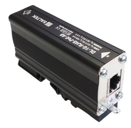
| Surge protection | ||
| OTH-DL-1GRJ45 | Surge protection 1Gb Eth Cat.6 LPZ0B-LPZ1 IP20 -40/+85°C | |
| OTH-DL-CAT.6-60V | Surge protection 1Gb Eth Cat.6 LPZ2-LPZ3 IP20 -40/+85°C | |
| CAT7 connector | ||
| CON-V01P-RJ45-FH | Connector RJ45 for Cat.7 outdoor IP67 -40/+70°C Weidmüller – plastic body | |
| CON-V01M-RJ45-FH | Connector RJ45 for Cat.7 outdoor IP67 -40/+70°C Weidmüller- metal body | |
| CON-RJ45-FH-BK | Connector RJ45 for Cat.7 indoor IP20 -40/+70°C Weidmüller – indoor | |
| CAT7 cable | ||
| CAB-S/FTP 4x | Cat.7 cable for connecting FOD units to the network, PEWTRONIC Ltd. | |
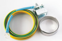
| RAy grounding kit | ||
| KIT-GROUNDING-1/4″ | Grounding kit for antenna cable | |
| KIT-GROUNDING-RAY | Grounding kit for mast grounding | |
| Antenna | 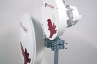 | |
The overview of different Jirous antenna types is listed in Section 3.5, “Dimensions”. The antenna choice determines radio link properties. The radio link calculation should be performed to determine proper antenna size. Rough calculation can be done using a simple on-line calculator.
| ||
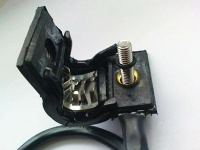
| Antenna mounting kit | 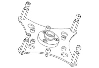 | |
Other manufacturer’s antennas can also be used with RAy2 links. The RAy2 unit can be attached by means of special interconnetions. There are several types of these parts for Andrew and Arkivator antennas. It is also possible to develop interconnetions for other antenna types.
| ||
Flexible waveguide mounting kit | 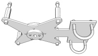 | |
The RAy unit can be attached to the antenna by flexible waveguide.
| ||
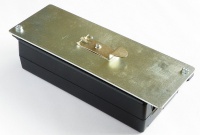
Power supply PoE |  | |
| ||
Surge protection | 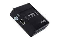 | |
| ||
|  | |
CAT7 connector |  | |
| ||
CAT7 connector indoor | 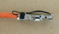 | |
| ||
CAT7 cable | 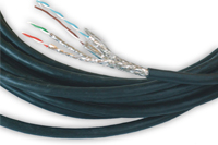 | |
| ||
Extended descriptions
See www.racom.eu, Microwave link, Accessories