Bridge mode enables transparent data transfer over the RipEX2 network. It is suitable for Point-to-Multipoint networks, where Master-Slave applications with polling-type communication protocol are used. The Bridge mode is suitable also for Point-to-Point links (both half and full duplex).
One of the advantages of the Bridge mode (together with Radio Transparent protocol) is its transparency. For example: both IPv4 and IPv6 type of traffic passes through; Frames defined by IEEE802.1Q-2018 are supported (e.g. VLAN, QinQ).
Bridge mode operation depends on the following system settings:
Radio channel: Transparent protocol selected
Ethernet ports: The Ethernet ports, intended to be used in Bridge mode, are grouped together in the Network interface (default name “bridge”), which is bridged with the Radio interface (parameter “Bridged with radio” enabled)
COM ports: “Transparent protocol” selected
Radio channel
Transparent radio channel protocol does not solve collisions. There is a CRC check of data integrity to assure once a message is delivered, it is error free.
Ethernet ports
The whole radio network build from RipEX2 radio modems behaves as a standard Ethernet bridge. An Ethernet bridge (“Network interface” in RipEX2) automatically learns which devices (MAC addresses) are located in the local LAN and which devices are accessible over the radio channel. Consequently, only the Ethernet frames addressed to remote devices are physically transmitted over the radio channel. This arrangement saves the precious RF spectrum from extra load which would be otherwise generated by local traffic.
By default all Ethernet ports are bridged together with the Radio interface. It is possible to remove some Ethernet ports from this Network interface (having the Radio interface attached) to prevent unwanted traffic to enter the radio channel.
At least one Eth interface has to be bridged with the Radio
It is possible to form another Network interface(s). Any needed Ethernet traffic can be routed in between individual Network interfaces.
It is a good practice to detach one (or more) Ethernet port(s) from the main Network interface (described above) for other purpose than transparent data transfer. One typical example is: dedicated port for the unit management. It is very useful to use such a separated port for unit management, because there is no danger of transferring unwanted traffic (e.g. system updates or similar traffic) from the client PC over the radio channel. You can create another Network interface (e.g. called LAN-mgmt). Attach the previously detached ETH port and configure an IP address to be able to access the unit management.
COM port
The COM port needs to be Enabled and a Protocol needs to be selected to transfer any data. “Transparent” type of COM protocol is dedicated for Bridge mode purposes. This protocol transfers data between the COM port and the RipEX2 network transparently. Any other Protocol can be selected when needed.
When the “Transparent” protocol is selected, all frames received from the COM port are broadcasted over the radio channel and transmitted to all COM ports on all radio modems within the network. If the remote COM port is also configured for “Transparent” protocol, the received data are transparently transmitted over the COM port.
Terminal Servers
Behavior of Terminal Servers is similar to COM port. “Transparent” protocol needs to be selected when transparent data transfer to whole network (broadcasts) is needed. The other protocol types can be used for “Router mode” type of addressed communication.
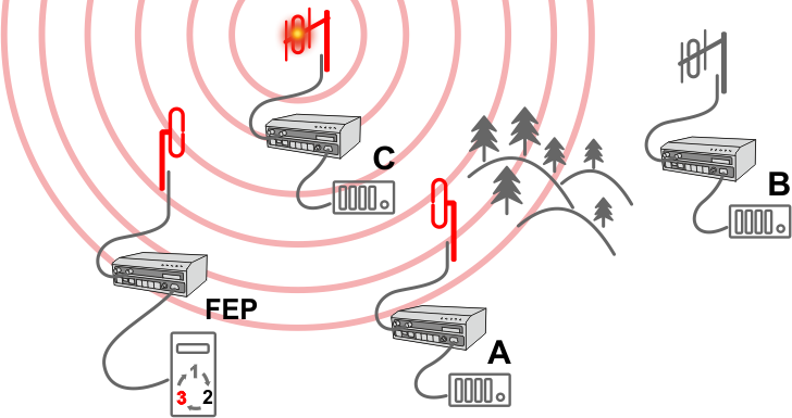
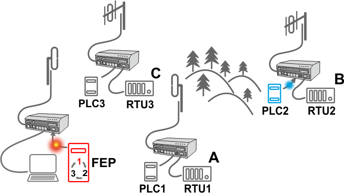
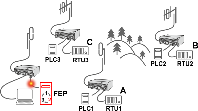
In the following, common acronyms from SCADA systems are used:
FEP – Front End Processor, designates the communication interface equipment in the center
RTU – Remote Telemetry Unit, the terminal SCADA equipment at remote sites
The single digits in illustrations are “site names” and do not necessarily correspond with actual addresses of both the RipEX2‘s and SCADA equipment. Address configuration examples are given in the Section 5.1.2, “Configuration examples”.
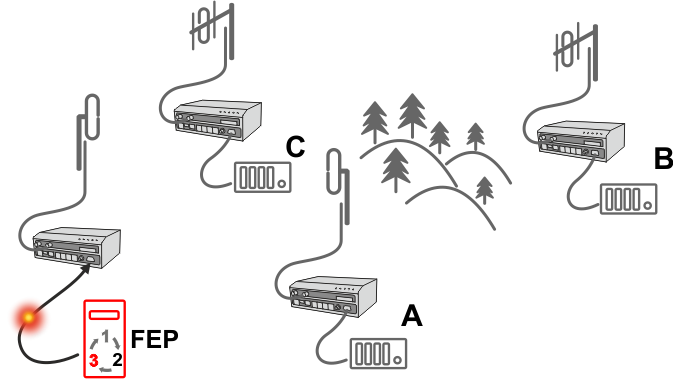 |
Step 1 Polling cycle starts: |
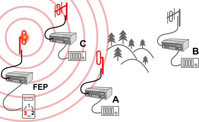 |
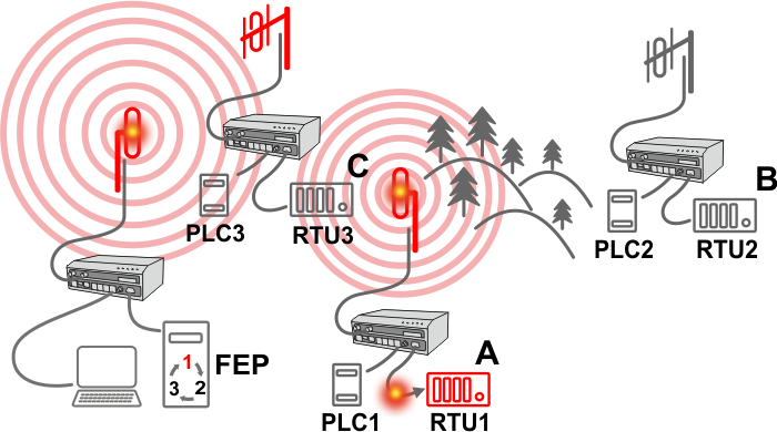
Step 2 RipEX2 FEP broadcasts this packet on Radio
channel. |
 |
Step 3 RipEX2 C and RipEX2 A send the received packet to their COM
ports. |
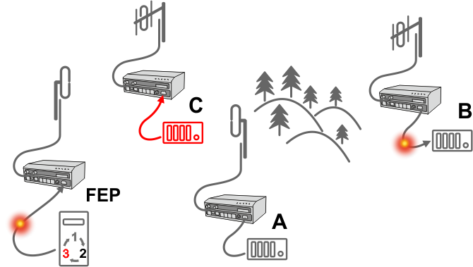 |
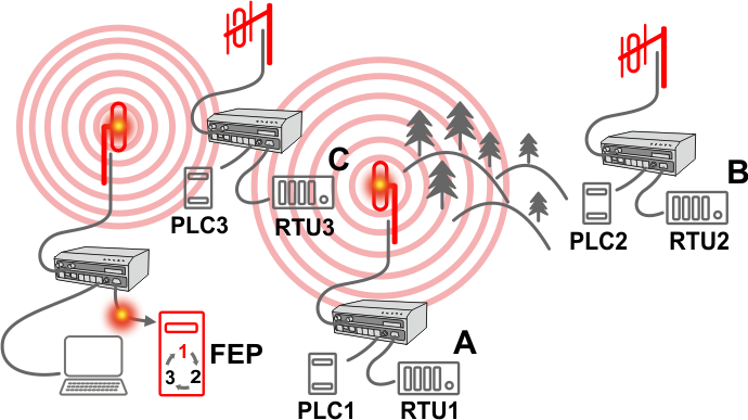
Step 4 RipEX2 B sends repeated packet to its COM. |
 |
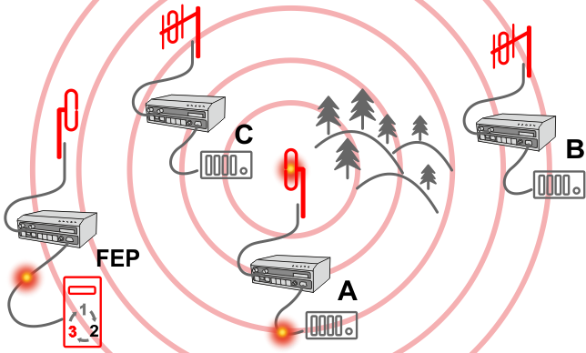
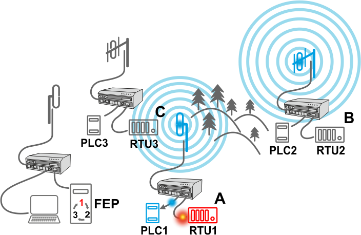
Step 5 RipEX2 C broadcasts the reply packet from RTU C on Radio
channel. |
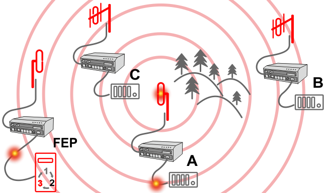 |
Step 6 RipEX2 FEP sends the packet (the reply from RTU C) to FEP through
COM. |
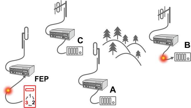 |
Step 7 RipEX2 B sends repeated packet to its COM. |
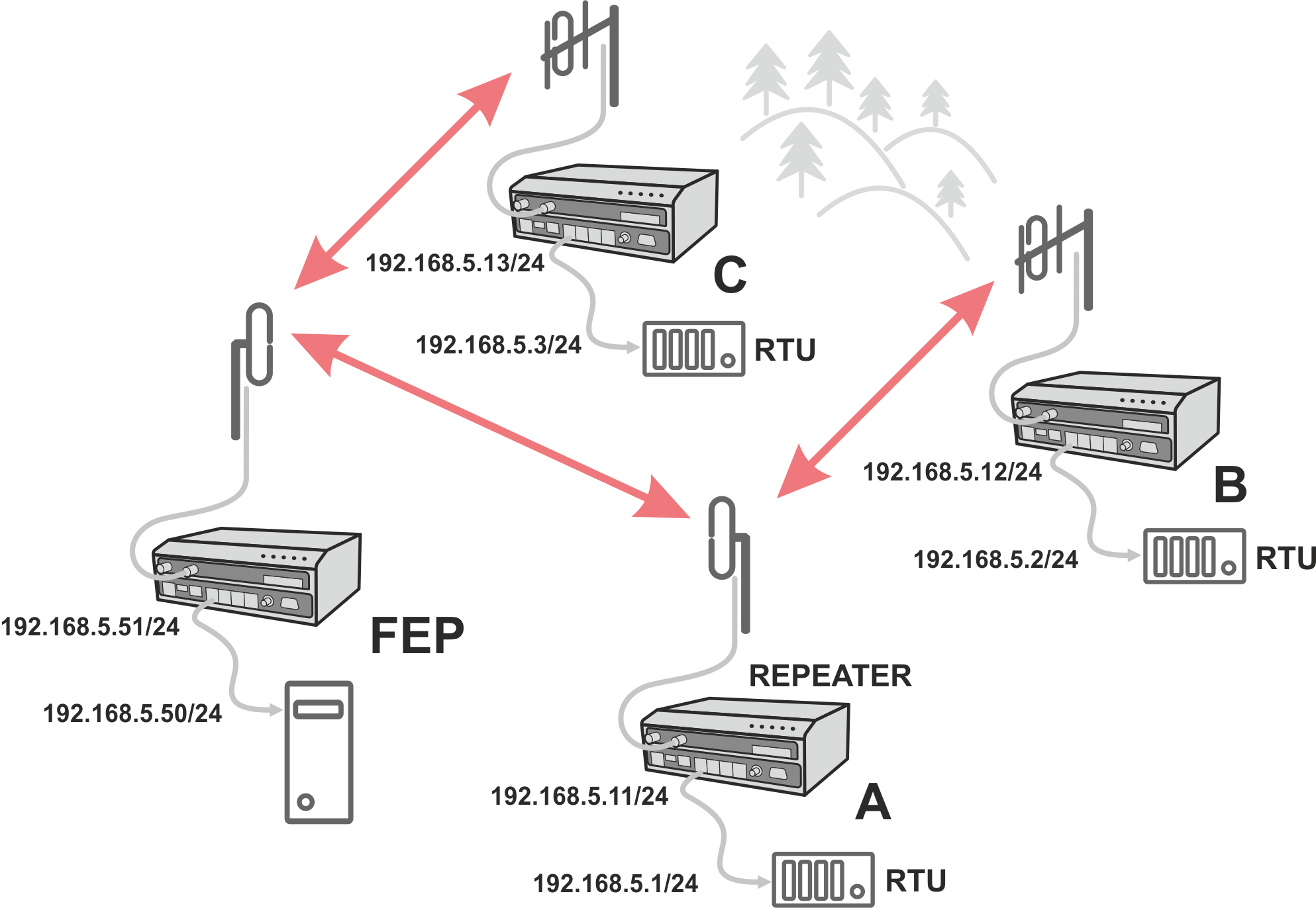
You can see an example of IP addresses of the SCADA equipment and RipEX2 ETH interfaces in the picture below.
In Bridge mode, the IP address of the ETH interface of RipEX2 is not relevant for user data communication. However it is strongly recommended to assign a unique IP address to each RipEX2 Network interface, since it allows for easy local as well as remote service access. Moreover, leaving all RipEX2 units with the same (= default) IP on the ETH interface may cause serious problems, when more RipEX2 units are connected to the same LAN, even if by accident (e.g. during maintenance).
Repeater
Because using the bridge mode makes the radio network transparent, the use of repeaters has certain limitations. To keep matters simple we recommend using a single repeater. However, if certain rules are observed, using multiple repeaters in the same network is possible.
The total number of repeaters in the network is configured for every unit individually under SETTINGS > Interfaces > Radio > Radio protocol parameters. This information is contained in every packet sent. All units that receive such packet will resume transmission only after sufficient time has been allowed for the packet to be repeated. The packets received from user ports remain buffered and are sent after the appropriate time passes. This prevents collisions between remote radio modems. There can be no repeater collisions if only one repeater is used.
Where two or more repeaters are used, collisions resulting from simultaneous reception of a repeated packet must be eliminated. Collisions happen because repeaters repeat packets immediately after reception, i.e. if two repeaters receive a packet from the center, they both relay it at the same time. If there is a radio modem which is within the range of both repeaters, it receives both repeated packets at the same time rendering them unreadable.
To establish a PtP link it is recommended to use a Bridge mode. In context of PtP it has following advantages:
Simple configuration
Transparent data transfer (VLAN – single, double, tripple tagged; IPv6; MPLS; etc.)
Possibility of using Full duplex
Low latency
In case of using Full duplex, it is required to:
Install a duplexer (exact type for a given channel link). A recommended duplex distance is 75 dB and more.
Due to high duty cycle, proper cooling is required. We recommend to use RipEX2-RS.
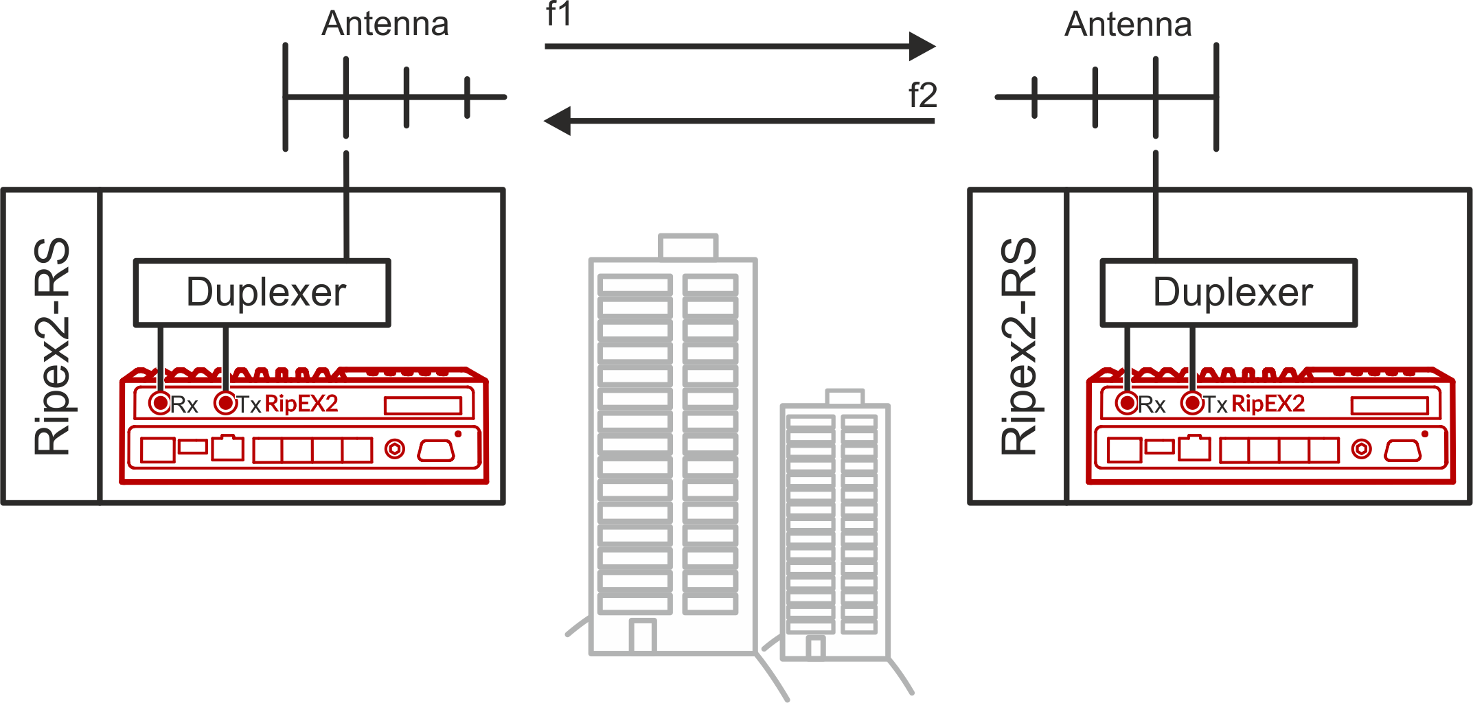
For more details see RipEX2 PtP link tutorial video.
RipEX2 works as a standard IP router with multiple independent interfaces: Radio and Ethernets. Each interface has its own MAC address, IP address and mask.
IP packets are processed according to routing table rules. You can also set the router’s default gateway (applies to both interfaces) in the routing table.
The COM ports are treated as standard host devices, messages can be delivered to them as UDP datagrams to selected port numbers. The destination IP address of a COM port is either the IP of an ETH or the IP of a radio interface.
The additional Virtual COM ports and Terminal server can act as other IP router ports. This enables Serial and TCP based RTUs to be combined in one network.
Two different Radio protocols are available in the Router mode: Base driven and Flexible.
Base driven
This protocol is optimized for TCP/IP traffic and/or ‘hidden’ Remotes in report-by-exception networks, when a Remote is not be heard by other Remotes and/or different Rx and Tx frequencies are used. It is suitable for a star network topology with up to 255 Remotes under one Base station, where each Remote can simultaneously work as a Repeater for one or more additional Remotes.Flexible
Suitable for master or even multi master-slave polling and report by exception from remotes concurrently. No limits in network design – each radio can work as base station, a repeater, a remote, or all of these simultaneously
All traffic over the Radio channel is managed by the Base station. Radio channel access is granted by a deterministic algorithm resulting in collision free operation regardless of the network load. Uniform distribution of Radio channel capacity among all Remotes creates stable response times with minimum jitter in the network.
All communication on Radio channel is controlled by the Base station; all frames inside the radio network have to be routed through the Base station. Appropriate routing has to be set.
Base station can communicate with the Remote stations using individual modulation and FEC settings.
Any Remote can work as a Repeater for another Remote. Only one Repeater is possible between the Base station and Remote, however a number of Remotes can use the same Repeater.
There is no need to set any routes in Routing table(s) for Remote stations located behind Repeater. Forwarding of frames from the Base station over the Repeater in either direction is provided transparently by the Base driven protocol.
When Remote to Remote communication is required, respective routes via the Base station must be set in Routing tables in the Remotes.
Frame acknowledgement, retransmissions and CRC check, guarantee data delivery and integrity even under harsh interference conditions on the Radio channel.
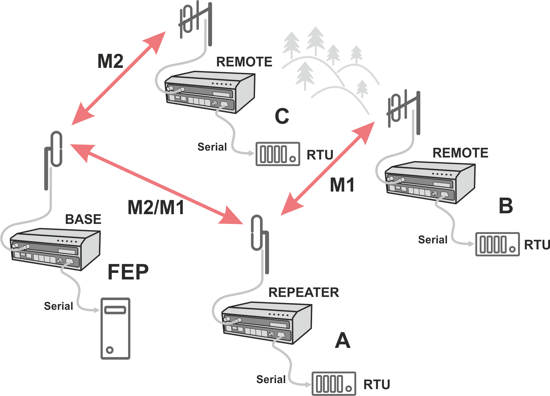
A star topology with one repeater is used in the following example of a SCADA network using a polling and report by exception combination. The Repeater is also serving as a Remote radio. The packets’ acknowledgement on Radio channel is used in both directions in the example.
Step 1
RipEX2 base station regularly checks the queue status of
RipEX2 Remote stations for which it has no queueing information. The feedback
enables the Base station to manage time allocations for all Remotes to transmit.
Step 2
FEP sends a request packet to RTU A via Base station; Base station
transmits packet in shortest possible time. Remote station 1 receives the packet and hands
it over to RTU A, simultaneously acknowledging packet receipt to the Base station.
Step 3
RTU A processes the request and sends the reply to Remote station
1. During the checking process the Base station detects a prepared packet in the queue of
Remote station 1 and subsequently allots a Radio channel for transmission of the packet.
Remote station 1 transmits the packet. If the Base station successfully receives the
packet, it sends an acknowledgement and then the Remote station 1 clears the packet from
the queue. A part of the relation includes a hand over of information about the number of
packets waiting in the queue.
Step 4
RTU B is connected to Remote station 2 behind Repeater station 1,
which manages all communication between the Base station and Remote station 2.
As already mentioned, RipEX2 works as a standard IP router with multiple
independent interfaces: Radio and Ethernets. Each interface has its own MAC address, IP
address and mask.
When Base driven protocol is used, Radio IP addresses for
all RipEX2 units must share the same IP subnet.
The Base driven protocol routing table for each RipEX2 Remote station can be
simplified to a default gateway route rule directed to RipEX2 Base station Radio
IP. Only one record with respective IP address/mask combination for each remote station is
needed in the Base station routing table.
The repeaters are not considered in
routing in Base driven protocol. Each Remote station uses its own Radio IP address as a
gateway in the routing table of the Base station.
| Important | |
|---|---|
For those accustomed to using the Flexible Radio protocol: |
| Note | |
|---|---|
When only serial protocols are used, there is no need to use Routing tables. Instead of using Routing tables records, Address translation in COM protocol settings is used. Serial protocol address to IP address translation rules apply where the Radio IP addresses are used. Radio IP addresses will only be used for maintenance in such circumstances. |
Router mode with Flexible protocol is suitable for Multipoint networks of all topologies with unlimited number of repeaters on the way, and all types of network traffic where Multi-master applications and any combination of simultaneous polling and/or report-by-exception protocols can be used.
Each RipEX2 can access the Radio channel spontaneously using sophisticated algorithms to prevent collisions when transmitting to the Radio channel. Radio channel access is a proprietary combination of CSMA and TDMA; the Radio channel is deemed to be free when there is no noise, no interfering signals and no frames being transmitted by other RipEX2 stations. In this situation, a random selection of time slots follows and a frame is then transmitted on the Radio channel.
Frame acknowledgement, retransmissions and CRC check, guarantee data delivery and integrity even under harsh interference conditions on the Radio channel.
In the following example, there are two independent SCADA devices connected to RipEX2‘s ports (COM and ETH). One is designated RTU (Remote Telemetry Unit) and is assumed to be polled from the center by the FEP (Front End Processor). The other is labelled PLC (Programmable Logic Controller) and is assumed to communicate spontaneously with arbitrary chosen peer PLCs.
 |
Step 1 FEP sends a request packet for RTU1 through COM to its connected
RipEX2. |
 |
Step 2 FEP’s RipEX2 transmits an addressed packet for RTU1 on Radio
channel. |
 |
Step 3 RipEX2 2 waits untill previous transaction on Radio channel is
finished (anti-collision mechanism). |
 |
Step 4 RipEX2 1 transmitts the reply packet from RTU1 for FEP on Radio
channel. |
 |
Step 5 FEP receives the response from RTU1 and polling cycle
continues… |
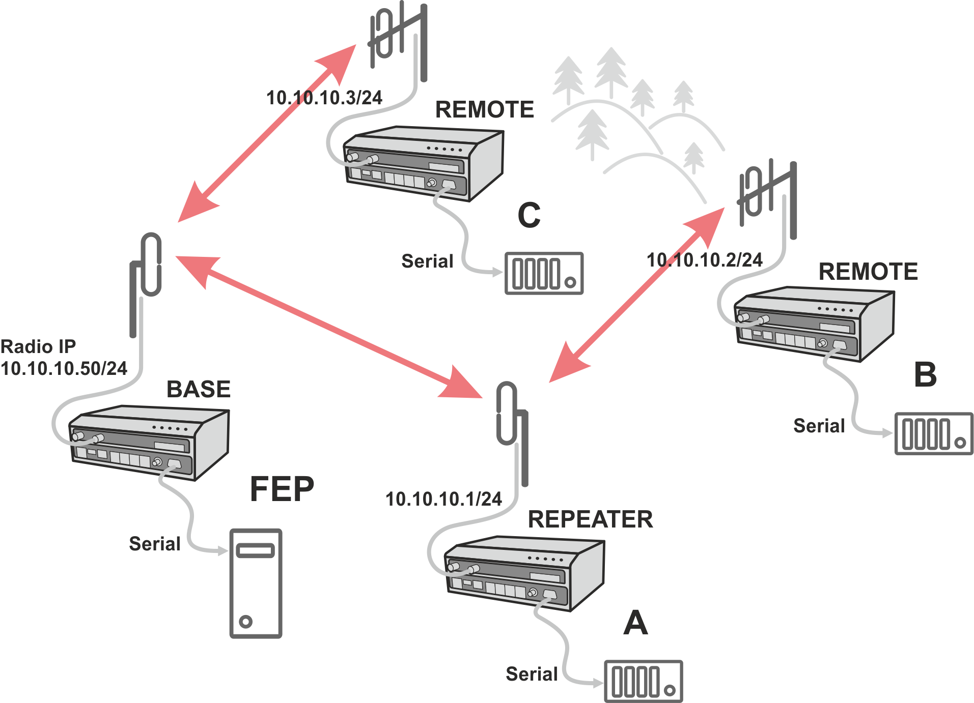
As it was mentioned above, RipEX2 radiomodem works as a standard IP router with two independent interfaces: radio and ETH. Each interface has got its own MAC address, IP address and mask.
The IP router operating principles stipulate that every unit can serve as a repeater. Everything what is needed is the proper configuration of routing tables.
Radio IP addresses of the RipEX2 units required to communicate over the radio channel must share the same IP network. We recommend planning your IP network so that every RipEX2 is connected to a separate sub-network over the Ethernet port. This helps to keep the routing tables clear and simple.
| Note | |
|---|---|
Even if the IP addresses of all RipEX2 units in a radio channel share a single IP network, they may not be communicating directly as in a common IP network. Only the RipEX2 units that are within the radio range of each other can communicate directly. When communication with radio IP addresses is required, routing tables must include even the routes that are within the same network (over repeaters), which is different from common IP networks. The example configuration below does not show such routing rules for the sake of simplicity (they are not needed in most cases). |
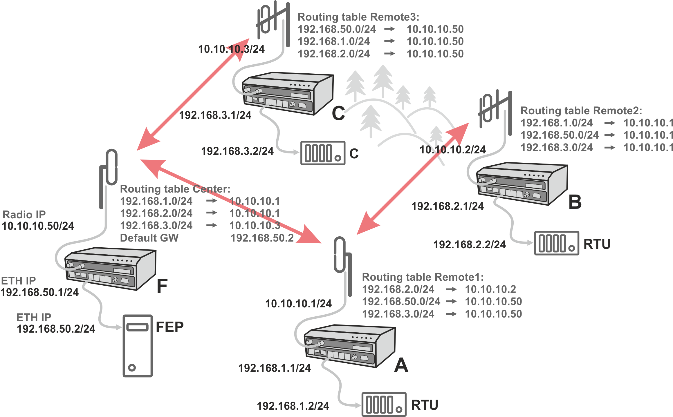
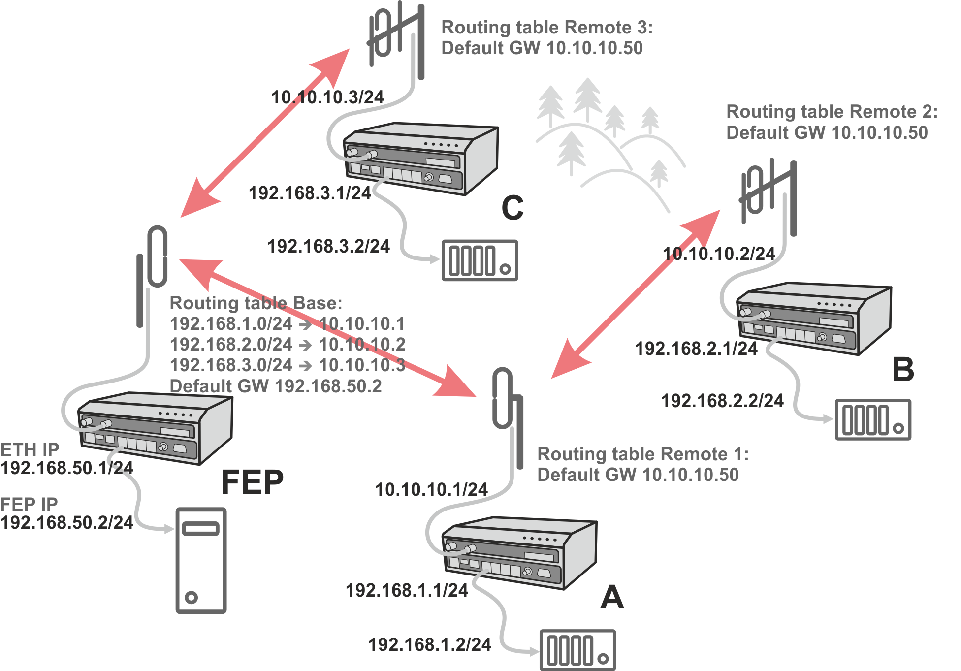
Formal consistency between the last byte of the radio IP address and the penultimate byte of the Ethernet address is not necessary but simplifies orientation. The “Addressing” image shows a routing table next to every RipEX2. The routing table defines the next gateway for each IP destination. In radio transmission, the radio IP of the next radio-connected RipEX2 serves as the gateway.
Example of a route from FEP (RipEX2 50) to RTU 2:
The destination address is 192.168.2.2
The routing table of the RipEX2 50 contains this record:
Destination 192.168.2.0/24 Gateway 10.10.10.1Based on this record, all packets with addresses in the range from 192.168.2.1 to 192.168.2.254
are routed to 10.10.10.1Because RipEX2 50’s radio IP is 10.10.10.50/24, the router can tell that the IP 10.10.10.1 belongs to the radio channel and sends the packet to that address over the radio channel
The packet is received by RipEX2 1 with the address 10.10.10.1 where it enters the router
The routing table of RipEX2 1 contains the record:
Destination 192.168.2.0/24 Gateway 10.10.10.2
based on which the packet is routed to 10.10.10.2 over the radio channelThe packet is received by RipEX2 2
The router compares the destination IP 192.168.2.2 with its own Ethernet address 192.168.2.1/24
and determines that the packet’s destination is within its ETH network and sends the packet over the Ethernet interface – eventually, the packet is received by RTU 2.
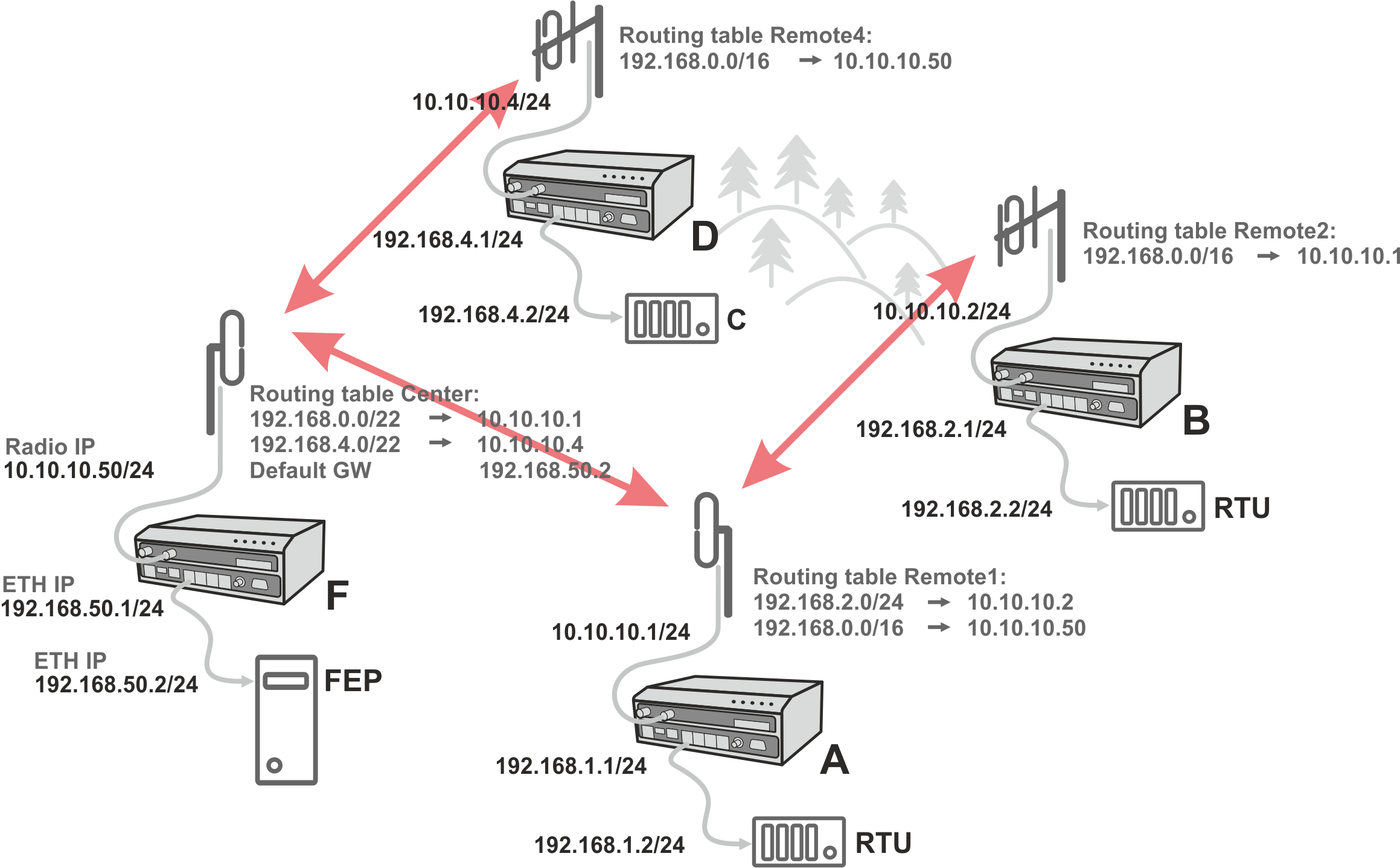
In large and complex networks with numerous repeaters, individual routing tables may become long and difficult to comprehend. To keep the routing tables simple, the addressing scheme should follow the layout of the radio network.
More specifically, every group of IP addresses of devices (both RipEX2‘s and SCADA), which is accessed via a repeater, should fall in a range which can be defined by a mask and no address defined by that mask exists in different part of the network.
A typical network consisting of a single center and number of remotes has got a tree-like layout, which can be easily followed by the addressing scheme – see the example in the figure “Optimised addressing” below.
The default gateway is also a very powerful routing tool, however be very careful whenever the default route would go to the radio interface, i.e. to the radio channel. If a packet to non-existing IP destination came to the router, it would be transmitted over the radio channel. Such packets increase the load of the network at least, cause excessive collisions, may end-up looping etc. Consequently the default route should always lead to the ETH interface, unless you are perfectly certain that a packet to non-existing destination IP may never appear (remember you are dealing with complex software written and configured by humans).
RipEX2 enables combination of IP and serial protocols within a single application.
Five independent terminal servers are available in RipEX2. Terminal server is a virtual substitute for devices used as serial-to-TCP(UDP) converters. It encapsulates serial protocol to TCP(UDP) and vice versa eliminating the transfer of TCP overhead over the radio channel.
If the data structure of a packet is identical for IP and serial protocols, the terminal server can serve as a converter between TCP(UDP)/IP and serial protocols (RS232, RS485).
Generally, a Terminal server (also referred to as Serial server) enables connection of devices with a serial interface to a RipEX2 over the local area network (LAN). It is a virtual substitute for the devices used as serial-to-TCP(UDP) converters.
Examples of the use:
A SCADA application in the center should be connected to the radio network via serial interface, however, for some reason that serial interface is not used. The operating system (e.g. Windows) can provide a virtual serial interface to such application and converts the serial data to TCP (UDP) datagrams, which are then received by the terminal server in RipEX2. This type of connection between RipEX2 SCADA and application is beneficial in the following circumstances:
There is no hardware serial interface on the computer
Serial cable between RipEX2 and computer would be too long. E.g. the RipEX2 is installed very close to the antenna to reduce feed line loss.
LAN already exists between the computer and the point of installation
![[Important]](/images/radost/images/icons/important.png)
Important The TCP (UDP) session operates only locally between RipEX2 and the central computer, hence it does not increase the load on the radio channel.
In special cases, the Terminal server can reduce network load from TCP applications. A TCP session can be terminated locally at the Terminal server in RipEX2. User data are extracted from the TCP messages and processed as if it came from a COM port. When the data reaches the destination RipEX2, it can be transferred to the RTU either via the serial interface or via TCP (UDP), using the Terminal server again. Please note, that RipEX2 Terminal server implementation also supports the dynamical IP port change in every incoming application datagram. In such a case the RipEX2 sends the reply to the port from which the last response has been received. This feature allows to extend the number of simultaneously opened TCP connections between the RipEX2 and the locally connected application up to 10 on each Terminal server.