This chapter is identical with the content of Helps for individual menu.
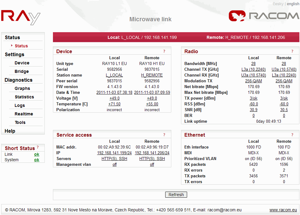
Device section provides basic information on the local and remote units. Please note, that the status page displays information valid at the moment of opening the page or pushing the “” button.
| Unit manufacturing label, conversion Unit type =
Ordering code: RAY10L1 = RAy10-LA (Low frequency part, band A) RAY10H1 = RAy10-UA (Upper frequency part, band A) RAY10H1EU = RAy10-UB (Upper frequency part, band B) RAY10H2EU = RAy10-UB-2 (Upper frequency part, band B, 2 connectors) The order code use U (Upper) letter for unit identification, instead of H (High), see Ordering code. | |
| Production serial No. Every unit has a unique serial number (a link consists of two units). | |
| Unit name assigned by user | |
| Unit location assigned by user The text is displayed trimmed to 14 characters followed by three dots. The tool-tip with whole text is given, when mouse pointer is located above the text. | |
| Serial No of the peer unit which is supposed to form the Point-to-Point link with the unit being configured. The red exclamation mark is displayed in the case of the disconnected radio link because of incorrect Peer serial, see Short Status. | |
| Firmware version and subversion | |
| The internal real-time clock. The clock is set manually or it is synchronized with SNTP server and is set identically in both units | |
| Voltage measurement at the input pins of the power supply connector | |
| Unit internal temperature | |
| The current state of the signal polarization (according to the physical installation of the unit). Local and Remote units are indicated separately to be able to check proper installation. The polarization is given by the orientation of the main handle-bar of the unit. The proper position of the cable is sideways down. |
Service access section provides basic information of the unit management options.
| HW address of the ethernet module | |
| IP address in the standard decimal “dot” notation, including the bit width of netmask after the forward slash. | |
| Enabled servers for service access (HTTPS and/or Telnet and/or SSH) | |
| Service access via management VLAN only |
Radio section provides basic information on settings and current state of the radio link.
| Nominal channel width. Both units in a link have to use the same bandwidth. | |
| Channels used, expressed both in GHz and channel Nos according to standard. | |
| TX modulation currently in use. Letters ACM are displayed when the Adaptive Coding and Modulation mode is set. | |
| Channel capacity currently available to the user | |
| The maximum RF channel capacity according to installed SW key. | |
| RF output power level currently used. If the transmission output is over 3 dBm lower than configured, then the red exclamation mark is displayed instead of letters ok, see Short Status. | |
| The intensity of the received signal is between −30 and −85 dBm. The weaker signal is identified as −110 dBm. | |
| Signal to Noise Ratio | |
| Bit Error Rate registered at the receiving end during the last second | |
| Time elapsed since the current link connection has been established |
Ethernet bridge section gives short overview of Ethernet interface settings and data flow.
| Status of the ethernet interface. Current bit rate (10 = 10BASE-T, 100 = 100BASE-TX and 1000 = 1000BASE-T) and state of duplex (FD = full duplex, HD = half duplex) is shown. The red exclamation mark is displayed in the case of the disconnected Ethernet link in the opposite unit, see Short Status. | |
| Status of internal crossover of twisted pairs of the ethernet cable (MDI-X = internally crossed pairs, MDI = direct connection, N/A means an unknown state). | |
| VLAN packets are permanently supported. The state “on (ID 4)” indicates the prioritized treating of the VLAN id 4 packets. The state “off” indicates that all VLAN packets are treated equal. | |
| Counter of all received packets. | |
| Counter of received packets containing errors. | |
| Counter of all transmitted packets. | |
| Counter of packets with errors during transmitting. |
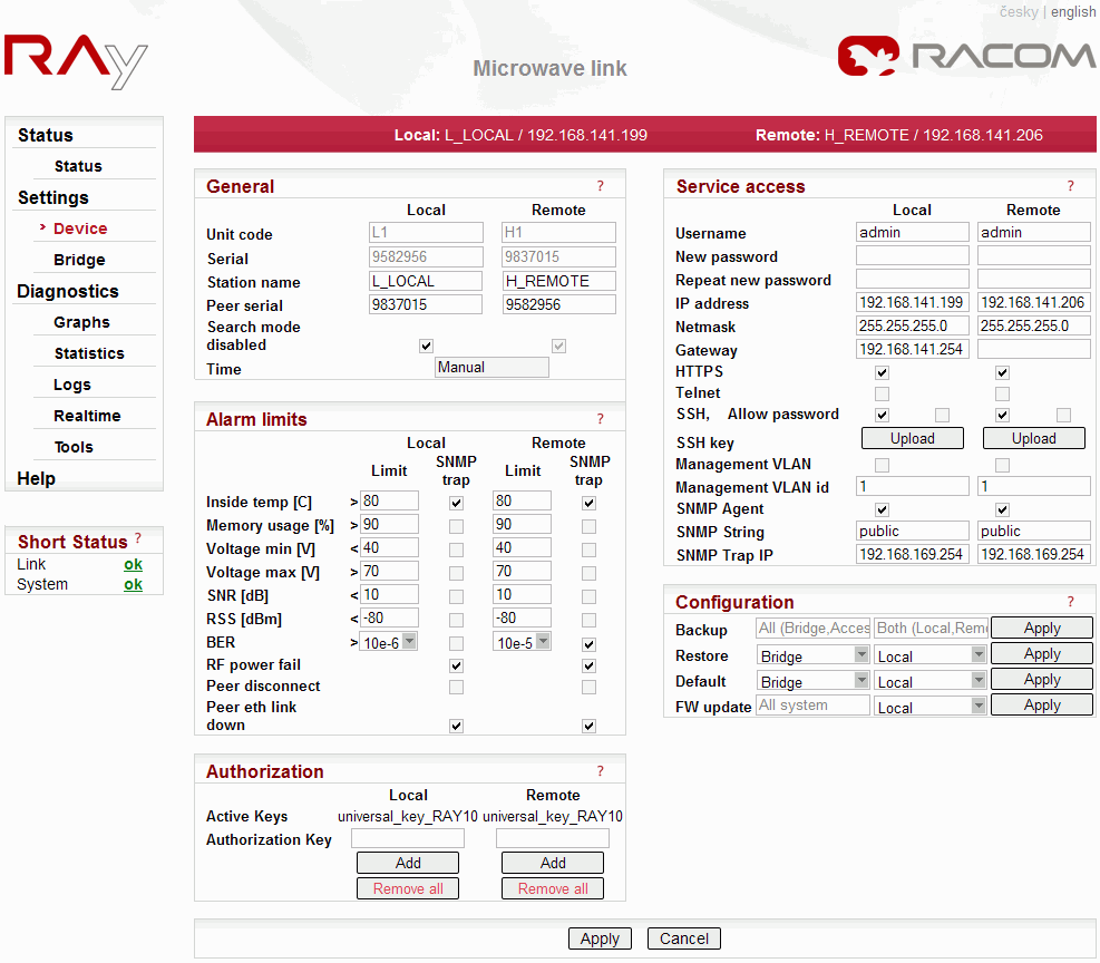
Section General contains fundamental system settings, including authentication parameters
| The unit code, e.g.: L1 – the Lower unit broadcasts in the lower group of channels H2 – the Upper unit broadcasts in the upper group of channels, 2 stands for two separate ethernet connectors, one for data and one for service access. The Ordering code use U (Upper) letter for unit identification, instead of H (High) . | |
| Unit serial number, unique for the H unit and the L unit. | |
| A name assigned to the device by user. Maximum length is 64 characters, the first character has to be a letter or a number and characters allowed are the letters of english alphabet a-z/A-Z, numbers 0-9 and two special characters “_” and “-“. | |
| The station location assigned to the device by user. Maximum length is 254 characters. The characters allowed are numbers 0-9, letters of english alphabez a-z/A-Z and special characters: “_.,:;/() -“. The quotation marks are NOT allowed. | |
| Serial No of the peer unit which is supposed to form the Point-to-Point link with the unit being configured. | |
Setting of this option has to be the same for both
Local and Remote units. Make this setting prior to unit
installation (especially when replacing damaged
unit):
| |
Clicking the Time box brings up the Time dialog window. The first selection is whether the time shall by synchronized manually or through the SNTP protocol from a time server.
– WARNING
– After clicking Ok in the Time window, the configuration has to be confirmed by clicking the main Apply button on the Device page |
Alarm limits section allows the user the set the limits on both link performance and environment conditions. Whenever a configured limit is reached, an alarm is written in the alarm log. At the same time, the Warning or Alarm appear in the Short Status. The consequent SNMP trap signal generation can be controlled individually for each item by checking the respective tick-box.
List of alarms and respective default limit values:
warning
| Inside temperature [°C] | >80 | Unit internal temperature high level alarm. |
| Memory usage [%] | >90 | System memory usage high level alarm. |
| Voltage min [V] | <40 | Supply voltage – low level alarm. |
| Voltage max [V] | >70 | Supply voltage – high level alarm. The SNMP trap is
common for both – high and low level alarms. The SNMP trap is common for both – high and low level alarms. |
| SNR [dBm] | <10 | Signal to noise ratio low level alarm. |
| RSS [dBm] | <-80 | Received signal strength low level alarm. |
alarm
| BER | >10-6 | Bit error rate high level alarm. |
| RF power fail | RF output power amplifier failure. | |
| Peer disconnect | Radio link to peer station is interrupted. | |
| Peer eth link down | User Ethernet link of the peer station is disconnected. |
Some RAy features may be controlled by the sw key installed. Typically the transmitted bitrate or power is limited by such key.
All valid keys in the station are listed here:
| |
| Text box for input of a key. | |
| The key activation button. The key typed in the text box will be activated in the respective (local or remote) unit immediatelly after clicking OK in the dialog box (there’s no need to use the Apply button). | |
| Before removing all keys, it is recommended to configure the link to comply with the limitations (i.e. 7 MHz bandwith, QPSK modulation with high coding strength and max. 3 dBm output power for Ray10). If the configuration left does not comply with the no-key limitations, the default configuration is forced in after the next restart of the unit, which may cause a disconnect of the radio link. Immediatelly after executing the “Remove all” command the state of the link does not change, except the ACM level dropping to the lowest speed (if ACM is configured). A new key should be entered and/or the configuration should be changed to comply with the active limitation, otherwise the link may be disconnected after the next restart. |
Service Access section gives full control over different ways to configure and manage the link.
| The login name selected by the user. Maximum length is 25 characters, the first character has to be a letter and characters allowed are the letters of english alphabet a-z/A-Z, numbers 0-9 and one special character “_”. | |
| The new password selected by the user. The length is 5 to 8 characters. The characters allowed are the letters of english alphabet a-z/A-Z, numbers 0-9 and four special characters “.”, “:”, “_” and “-“. | |
| A new password has to be repeated to avoid typing errors | |
| The service and management interface IP address,
default 192.168.169.169 in L station and 192.168.169.170 in H
station. Four 169.254.173.236/30 addresses are used for internal communication. Not be used as a service IP address. | |
The LLDP protocol is implemented for the sake of the
management IP address discovery. The LLDP protocol message is
sent as a broadcast every 60s with the following
informations:
The LLDP message can be captured and converted to human readable format by any LLDP client. The Wireshark IP traffic analyzing tool is a very nice tool for that purpose (both Windows and Linux license free versions are available). When using Wireshark – the Capture filter “ether proto 0x88cc” can be used to ease the job. | |
| The service and management interface netmask, default 255.255.255.0 | |
| The service and management interface default gateway, no gateway by default | |
| Tickbox to enable the HTTPS server. When disabling, remember that you will not be able to access the unit by web browser afterward! Enabled by the Open-access default. | |
| Tickbox to enable the Telnet server. Telnet server provides CLI (Command Line Interface) for simple telnet clients. Disabled by default. | |
| Tickbox to enable the SSH server. SSH server provides a secure CLI connection. It should be the only server left running when security of the link management is the primary concern. Enabled by both Open and Secure-access defaults. | |
| Enables SSH access by password. Disabled by the Secure-access default. | |
| Tickbox to enable service access only via the managent
VLAN (it disables access via untagged LAN packets). See
Management VLAN id below. This feature is disabled by
default. – WARNING – | |
| Managent VLAN id, default 1. This field has to be filled in even when the Management VLAN tickbox is not checked. | |
| SSH key is uploaded from a file. | |
| Enabling the SNMP agent to monitor the unit’s operation using traditional NMS (Network Management Systems). | |
| SNMP community string. Maximum length is 256 characters. The characters allowed are the letters of english alphabet a-z/A-Z, numbers 0-9 and four special characters “.”, “:”, “_” and “-“. | |
| An IP address to which SNMP trap datagrams are sent. |
Configuration section provides tools for saving/restoring configuration data to/from a file. The configuration data file can be edited by an ordinary text editor. Service Access section gives full control over different ways to configure and manage the link. The factory default setting Access open is shown.
| Complete configuration settings are saved to a file named ray.conf. The configuration file can be edited by any common text editor. | ||||||||||||||||||||||||||||||||||||
| ||||||||||||||||||||||||||||||||||||
| ||||||||||||||||||||||||||||||||||||
| ||||||||||||||||||||||||||||||||||||
| Note | |
|---|---|
If there is any problem with https certificate after completing the firmware upgrade, please see the Appendix F, Https certificate for further steps. |
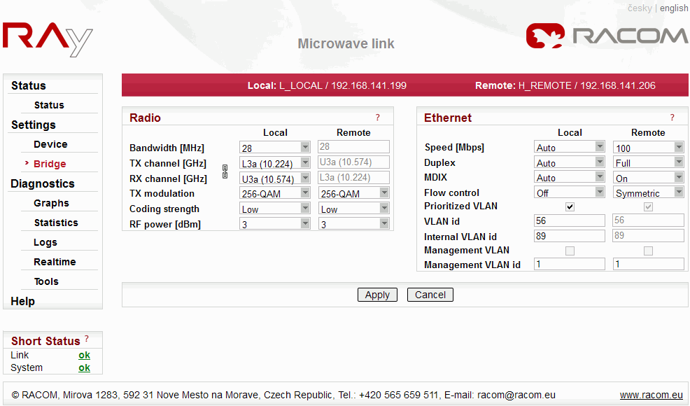
Radio link section comprises all necessary settings which influence the radio part operation. Some parameters (Bandwidth, Modulation, Coding strength and RF power) are influenced by installed Authorization Keys. See the menu Settings/Device/Authorization.
| One of standard channel widths can be selected. This parameter must be set identically in local and remote. | |
| TX and RX channel frequencies can be selected from the
list of available channels. Normally, the standard duplex
spacing is maintained, hence setting one channel box results
in automatic change of the remaining three. When special
conditions require different duplex setting than the standard
one, the TX-RX lock symbol may be unlocked. Then the TX and RX
channels can be set independently. The respective channel at
the peer side is again changed automatically. Warning: Non-standard duplex setting leads to non-effective use of the spectrum and should be used in well-justified cases only. RAy10-xB version: Channels are marked as L1a… according to CEPT/ERC/REC 12-05 E (2007). The “L” and “U” letters stand for the lower and upper segments of the range. The “a” index complies with CEPT standards, other indices “c”, “e”… identify shifted channels (in this case, by 7 MHz). This allows selecting channels according to other national standards. Channel identification also requires the bandwidth used – 28/14/7 MHz. For an overview of bandwidths and their mean frequencies refer to the manual – table of nominal frequencies. | |
| The desired modulation is selected from the list. When
ACM (Adaptive Coding and Modulation) mode is selected, the
modulation is selected automatically by the device, according
to the signal strength and quality. This way the link always
operates with the maximum bit rate allowed by signal
conditions, up to the limit given by the Authorization key.
When signal deteriorates, e.g. because of a heavy rain, the
modulation rate decreases (e.g. from 256-QAM to 128-QAM). That
results in the respective decrease of the throughput,
nevertheless the link is not interrupted
completely. The ACM always uses the coding=High, except when the maximum speed limited by the Authorization key corresponds to coding=Low. Then the Low coding is used for this maximum speed only. The ACM mode should be set on both units. The second possibility is the manualy set modulation on both units. The modulation can be set manualy from QPSK to 256-QAM, equally or differently on the unit L and H. | |
| The FEC (Forward Error Correction) coding is always
used over the RF channel. Its strength means its ability to
combat channel impairments, to avoid frame losses because of
data errors. The stronger the coding, the higher the overhead,
and consequently, the lower the net throughput. If the link
speed is your highest priority and your application can
tolerate slightly higher number of lost frames, you may want
to use weaker coding. Normally the stronger coding is the
recommended option. Note that when the ACM mode is configured, the coding is controlled automatically, hence the manual setting of it does not affect the link. | |
| The RF output power desired. To access the full power of +10 dBm, the rfPower Authorization Key has to be activated. Without the rfPower Key the power range is limited to +3 dBm. |
| One of the ethernet standards which determines bitrate can be selected (10BASE-T, 100BASE-TX or 1000BASE-T). “Auto” (default setting) allows automatic negotiation of bitrate with the wire-link peer. | |
| Possibility to select transmitting and receiving
simultaneously (full duplex) or one-at-a-time (half duplex) on
the ethernet link. “Auto” (default setting) allows automatic
negotiation of this feature with the wire-link
peer. Auto and 1000 speeds may only be used with Duplex auto settings. 100 and 10 speeds may be combined with Duplex full and Duplex half. | |
| Media Dependent Interface Crossover indicates the ability of the interface to crossover the twisted pairs of cable internally. “Auto” (default setting) allows automatically detect and set crossover if it is necessary (Auto-MDIX). | |
| Ethernet flow control is a mechanism for temporarily stopping the transmission of data on an ethernet network. | |
| RAy wireless bridge has the ability to specially treat VLAN packets. Selection “On” enables priority treatment of packets having the selected VLAN id (see below). | |
| Packets with this identification number in their VLAN header are preferentially treated when Prioritized VLAN “On” is set. | |
| The RF bridge uses one VLAN id for internal purposes.
It can be changed if there is a conflict with user data.
The L2/H2 version of the RAy uses internally one more VLAN id, which is set to value ‘Internal VLAN id’ plus 1. | |
| Tickbox to enable service access only via managent VLAN
(it disables access via untagged LAN packets). See Management
VLAN id below. This feature is disabled by
default. – WARNING
– | |
| Managent VLAN id, default 1. This field has to be filled in even when the Management VLAN tickbox is not checked. |
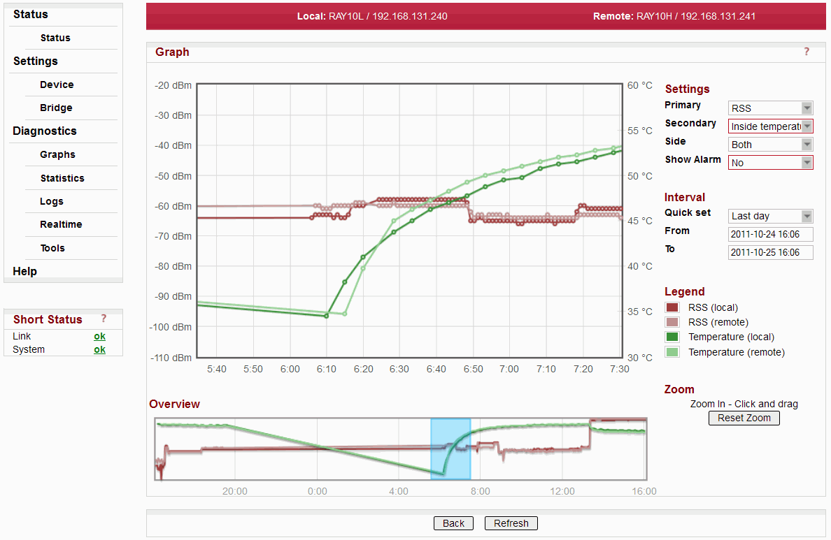
Graphs section provides graphical information on history of basic link parameters. The main page gives access to seven graphs:
RSS
BER
SNR
Internal temperature
Net bitrate
Voltage
Ethernet traffic
with last 24 hours course. Clicking one of the mini-graphs or selecting the desired parameter from the listbox opens the Detailed graph page.
| Primary parameter to be displayed | |
| Optional secondary parameter to be displayed in the same graph | |
| Graph from Local or Remote or Both ends of the link can be selected | |
| Active alarms are indicated on the graph time axis | |
| Time period displayed. To use time intervals it is recommended to synchronise the time zone and daylight saving settings in your PC and RAy unit. To do this, go to the Status /Device /Date&Time menu, and then use the Time submenu. The X, Y axes interval will be set up automatically using the extreme values of the monitored interval. For that reason, to display a Custom interval up to present, select Interval To greater than the present time. To refresh intervals Last hour, Last day… up to now you need to reload web page in your browser, the Refresh button itself is not enough. | |
| Legend explains meaning of the different colors | |
| Zoom in by dragging the mouse, get back to full scale by Reset zoom |
Refresh button applies selected changes
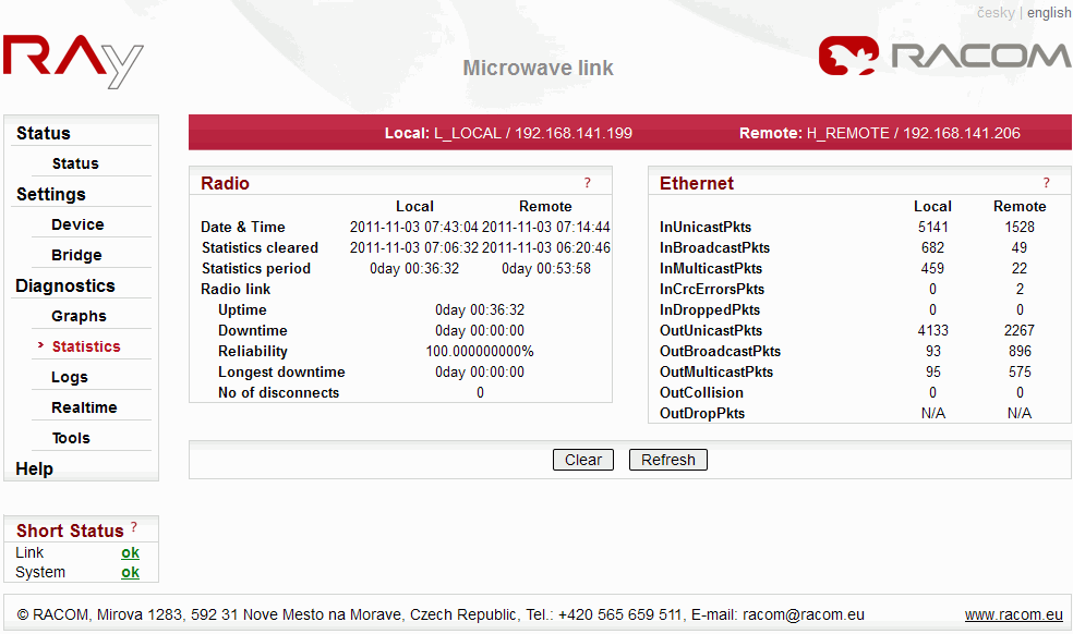
| Internal clock date and time | |
| Date and time of clearing the statistic counters | |
| Time elapsed from the clearing of the statistics |
Radio link
| Sum of time intervals when the radio link was connected | |
| Sum of time intervals when the radio link was disconnected | |
| “Uptime” to “Downtime” ratio | |
| The longest downtime period recorded | |
| Number of disconnect events |
Ethernet bridge
| Counter of unicast packets received | |
| Counter of broadcast packets received | |
| Counter of multicast packets received | |
| Counter of corrupted packets (CRC error) received | |
| Counter of received packets, which were discarded because of buffer overflow | |
| Counter of unicast packets transmitted | |
| Counter of broadcast packets transmitted | |
| Counter of multicast packets transmitted | |
| Counter of detected collisions during transmitting | |
| Counter of transmitted packets, which were discarded because of buffer overflow |
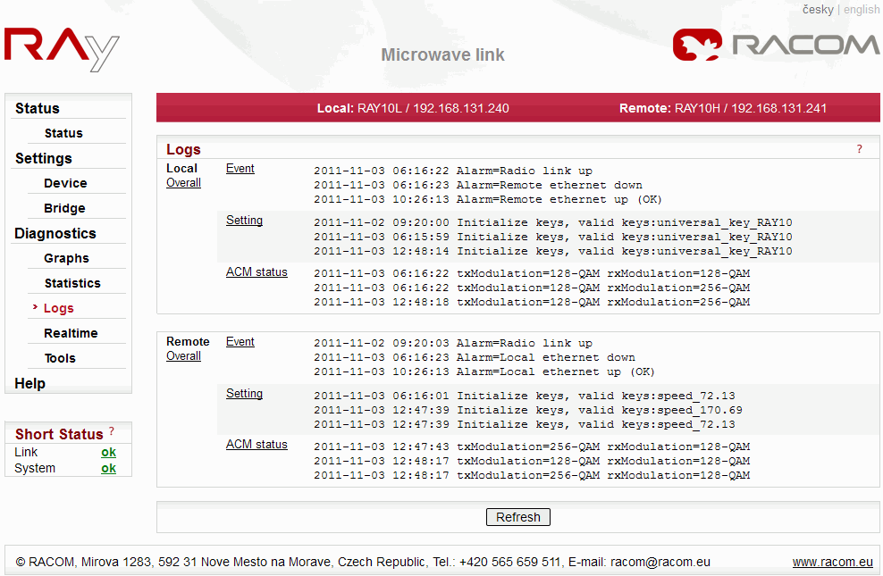
Last three records from the each log are displayed. The complete log is accessible by clicking the respective log name. The Local Overall and Remote Overall titles brings the respective overall log.
| Warning and Alarm states, see Alarm limits and Short Status. | |
| Configuration changes log. | |
| ACM switching log. | |
| Unsorted overview of the whole log. Last three records from the each log are displayed. The complete log is accessible by clicking the respective log name. |
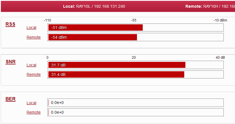
The values of RSS, SNR and BER are updated with a period of 1 second.
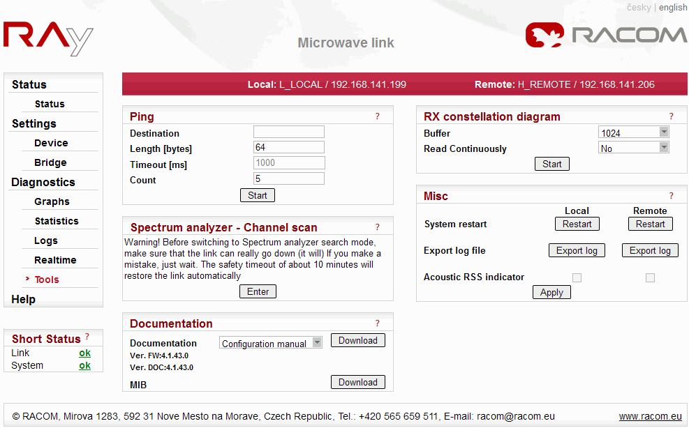
Ping is the simplest tool to check the connection to any member of the network
| Destination IP address (numerical only, in dotted decimal notation format) | |
| Random data bytes sent in the ping packet, 8 byte header will be added in the result | |
| Pings are always transmitted in 1000 ms period | |
| Number of pings which will be transmitted (0 means continuous transmission) |
Complete report is displayed after clicking the Refresh button
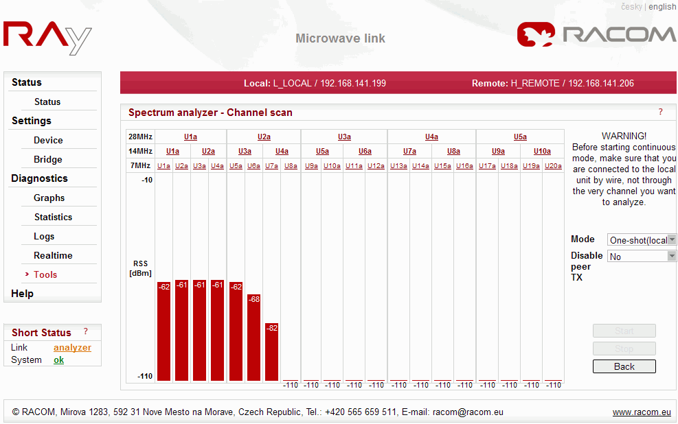
A very useful tool to evaluate in-band interference and to locate a free channel at a site. This is not a full-blown spectrum analyzer. The spectrum is only scanned with 7MHz channel resolution. The spectrum measurement accuracy is limited by RSS measurement accuracy.
| Enter the Spectrum analyzer menu. |
| Warning | |
|---|---|
BEWARE! Whenever the Spectrum analyzer mode is activated by clicking the Start button, the RF link is disconnected. The unit is switched to receive-only mode, bandwidth set to 7 MHz and all channels are scanned. The recorded RSS is then graphically displayed. The One-shot mode results in only about 20 sec interruption of the RF link and can be activated even at the remote end of the link. The Continuous mode is intended for use during a site survey and/or installation. It is automatically cancelled after 10 minutes to avoid permanent link shutdown by mistake. The peer TX transmitter can be optionally disabled in all modes. BEWARE! Before starting the “Continuous” mode, make sure you are not connected to the “local” unit through the very link you want to analyze. |
| A listbox to select the scanning mode. “One-shot” does one scan of all channels and automatically restores the RF link to normal operation. “Continuous” means the scanning is done repeatedly until the “Stop” button is clicked or the safety timeout of 10 minutes expires. | |
| The opposite end transmitter can be switched off during the scan. This is a very useful option for detecting an in-channel interference. In continuous mode the switch-off period has to be selected (10 sec – 10 min) before starting the analyzer. Note that the RF link can not be restored before the switch-off period expires, even if you stop the analyzer manually. | |
| Click the button to start the actual scanning. After, and only after, clicking this button the link will go down. | |
| Click the button to stop the scanning in continuous mode. If the peer transmitter is on, the link will be restored within few seconds. | |
| Click the button to leave the Spectrum analyzer screen. | |
| If you choose a range by clicking in the upper rows, you can use it to configure the link by clicking the OK button. The frequency will change after you click the Apply button in Bridge Settings. This function applies to One-shot (local) and Continuous (local) modes but not to One-shot (remote). |
The results of the Spectral analyzer are merely informative. RAy10 is not a properly calibrated measuring instrument. It cannot, for instance, be used to evaluate the compliance of a remote transmitter’s channel mask with a prescribed standard.
Documentation
The pdf format manuals can be downloaded directly from the RAy unit:
RAy10 Configuration manual – EN
RAy10 Konfiguracni manual – CZ
RAy10 Installation manual – EN/CZ
The content of those documents is the same as content of the User manual accessible at https://www.racom.eu. Some chapters (“Implementation notes”, “Safety, environment, licencing” and some attachments) were omitted to reduce the size of the pdf files. The complete manual can be downloaded from https://www.racom.eu/eng/products/m/ray/index.html
MIB
The MIB table can be downloaded directly from the RAy unit.
Constellation diagram is a powerful tool to assess the received signal quality. Samples of the demodulated signal are displayed along amplitude and phase coordinates. Ideally a perfect grid of single points should be seen. The degree of random dispersion indicates the distortion and noise in the channel. The smaller the gaps between neighboring groups of points are, the higher is the probability of an error.
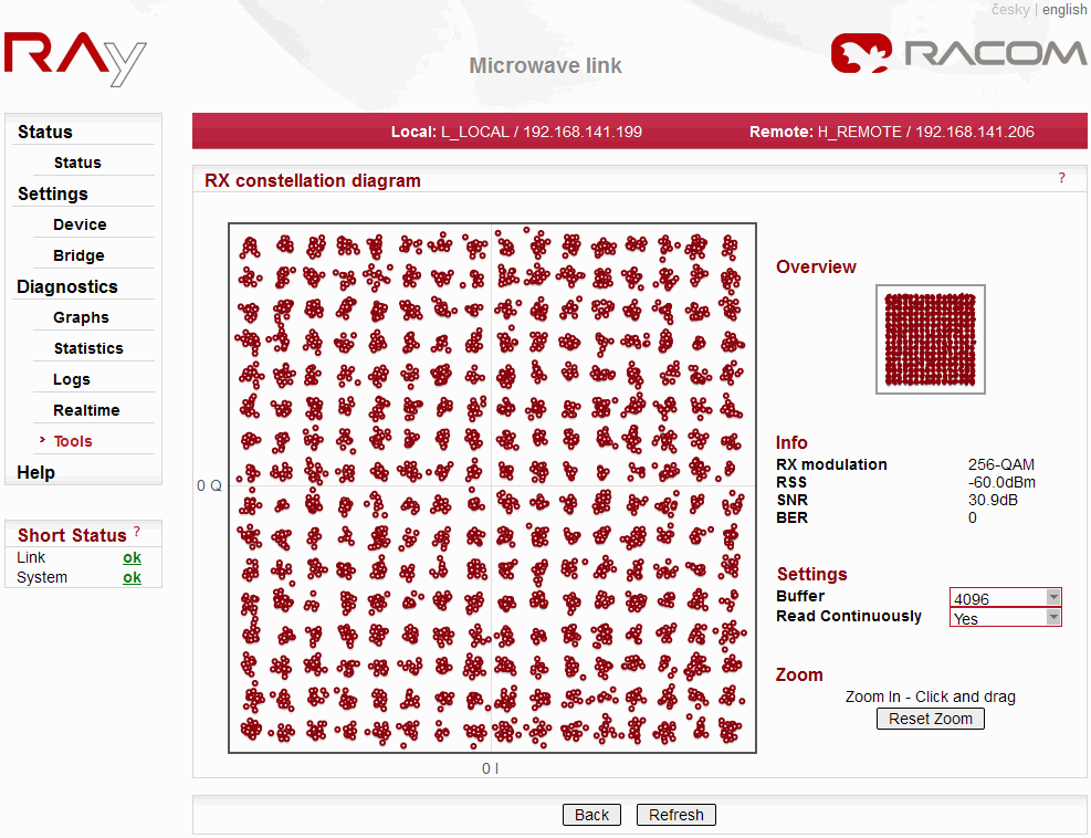
| Number of signal samples shown in one image | |
| The diagram is updated every couple of seconds | |
| Basic parameters of received signal (Modulation, RSS, SNR, BER) |
Zoom in is possible by dragging the mouse, getting back to full scale by Reset zoom.
Internet Explorer’s performance while displaying the RX constellation diagram is very poor (it takes minutes); we recommend using another browser, such as Mozilla Firefox, Opera or Chrome.
| Hard reset. | |
| Special diagnostic package (configuration and system logs) can be exported for service purposes. | |
| The built-in acoustic indicator of RSS is an optional feature. It can be used for the final adjustment of the antenna. Even a small difference in the RSS is reflected in the tone frequency – the higher the pitch, the stronger the signal. The beeper is switched on only after clicking the Apply button. Remember to switch it off after completing the work. It automatically switches off after 30 minutes. |
The Short Status is refreshed automatically every 3 seconds.
| |||||||||
|