Standard RAy3 unit configuration and management are made through its web-based graphical user interface (GUI). All functions, their parameters, configuration possibilities and options are described within this chapter.
All functions described in this chapter are also available through the unit CLI interface – for its description see Chapter 6, Command Line Interface.
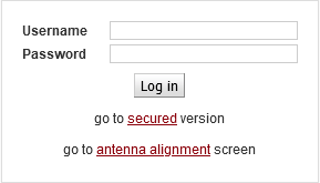
Unit can be easily managed from your computer using a web browser. If there is an IP connection between the computer and the respective unit, you can simply enter its IP address directly in the browser address line and log in.
Port forwarding may also be used to connect to Peer unit (in case the link is established) by entering the IP address of the Local unit and one of the following ports: 8022, 8023, 8080, 8161 and 8443.
Supported web browsers for desktops are current versions of:
Edge
Chrome
Firefox
Safari (for iOS only)
Supported Web browsers for smartphone equipment are current versions of:
Chrome (for Android only)
Safari (for iOS only)
| Note | |
|---|---|
For safety reasons, it is recommended to use a web browser without any extensions (especially extensions, which could get access to data). |
For the sake of security only HTTPS protocol is used for the connection between the web browser and RAy3 unit. If the http://… is used into the web browser address line, the communication is immediately automatically redirected to HTTPS protocol.
| Note | |
|---|---|
Antenna alignment link below Login window activates smartphone Antenna alignment tool. See its detailed description in chapter Live data. |
The unit has several protections implemented against unauthorized login and brute force attacks:
Web inactivity timeout: The web session is automatically ended after a fixed period of inactivity to ensure security and efficiency. The timeout duration is set to 600 seconds.
Web sessions limit: The maximum number of simultaneously open web interface sessions is limited to 3.
Invalid login delay: After entering an incorrect password, another attempt is allowed only after a security delay. The delay gradually increases (from 0 to 25 seconds) after multiple unsuccessful attempts.
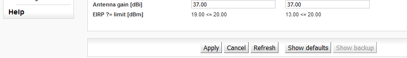
The following configuration buttons are used for configuration:
- Apply
Apply and save parameters.
- Cancel
Set parameters are overwritten with original values.
- Refresh
Reload all current values of the unit / both units.
- Show defaults
Clicking the button displays the default values of all individual parameters on the current screen. To use these values, you must click on the “Apply” button.
- Show backup
Clicking the button displays the values of individual parameters downloaded from the backup file (Backup > Settings > Open file upload). To use any of these values, you must use the “Apply” button. For loading the backup configuration see menu Tools/Maintenance > Backup.
- Start
Activating automatic refresh fields marked by
 icon using the Start button with the
frequency circa 1 sec.
icon using the Start button with the
frequency circa 1 sec.- Stop
Use the “Stop” button to stop automatic refresh of displayed information with 1sec period. Date and time values are refreshed anyway.
The microwave link configuration system is equipped with built in Help – see Help section. The Help is accessible in two forms:
Configuration parameter context help. The help text is displayed in the pop-up window after clicking the parameter name.
The whole user interface help, activated by clicking the Help menu.
If you interrupt the connection on an operating link by entering inappropriate radio link parameters, the original parameters will be restored after 1 minute. The connection should be automatically restored.
| Note | |
|---|---|
The only exception to the Rollback function is during the activation of ‘TX mute’ setting, which disconnects the link permanently (until this setting is manually de-activated). |
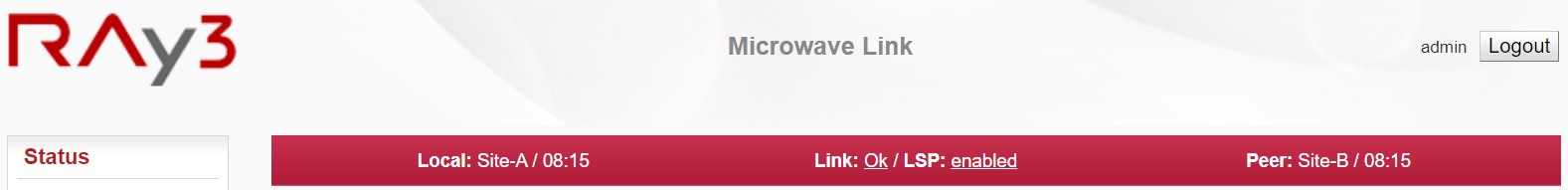
The Status bar is located on the upper part of the screen below the title bar. It consists of 4 fields:
Local unit status (unit assigned to the IP address entered in the browser or CLI)
Link status (Local to Peer)
LSP status
Peer unit status
In more detail:
Local and Peer status field displays:
- Station name
according to configuration
- Actual time
valid for respective unit
- Warning or Alarm icon
in case of warning or alarm
Link status field displays:
- Ok
if the link is connected, Peer unit is authorized and user data are transmitted
- or Warning icon (a triangle)
if the link is not capable of user data transfer,
followed by a status of the link (one of the following values):- Unknown
Unit start up. The initialization is not yet finished.
- Setup
Unit initialization according to valid configuration.
- Single
Unit in operation status. Link to peer unit is not established.
- Connecting
Connection to peer unit in progress.
- Authorizing
Authorization of the peer unit in progress.
- Analyzer
Spectrum analyzer mode active. User data are not transferred.
LSP status field displays:
- nothing displayed
LSP is not enabled
- enabled
LSP is enabled but not active
- activated
LSP is activated because the activation conditions have been met
The example of a complete Status bar with active Alarm and Link not OK.

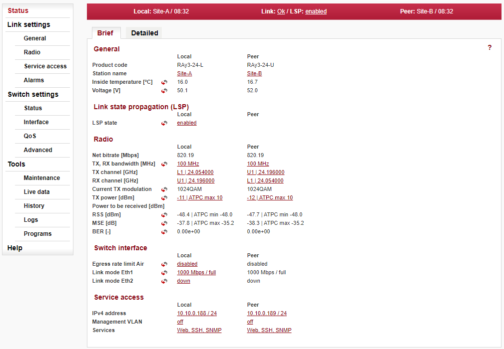
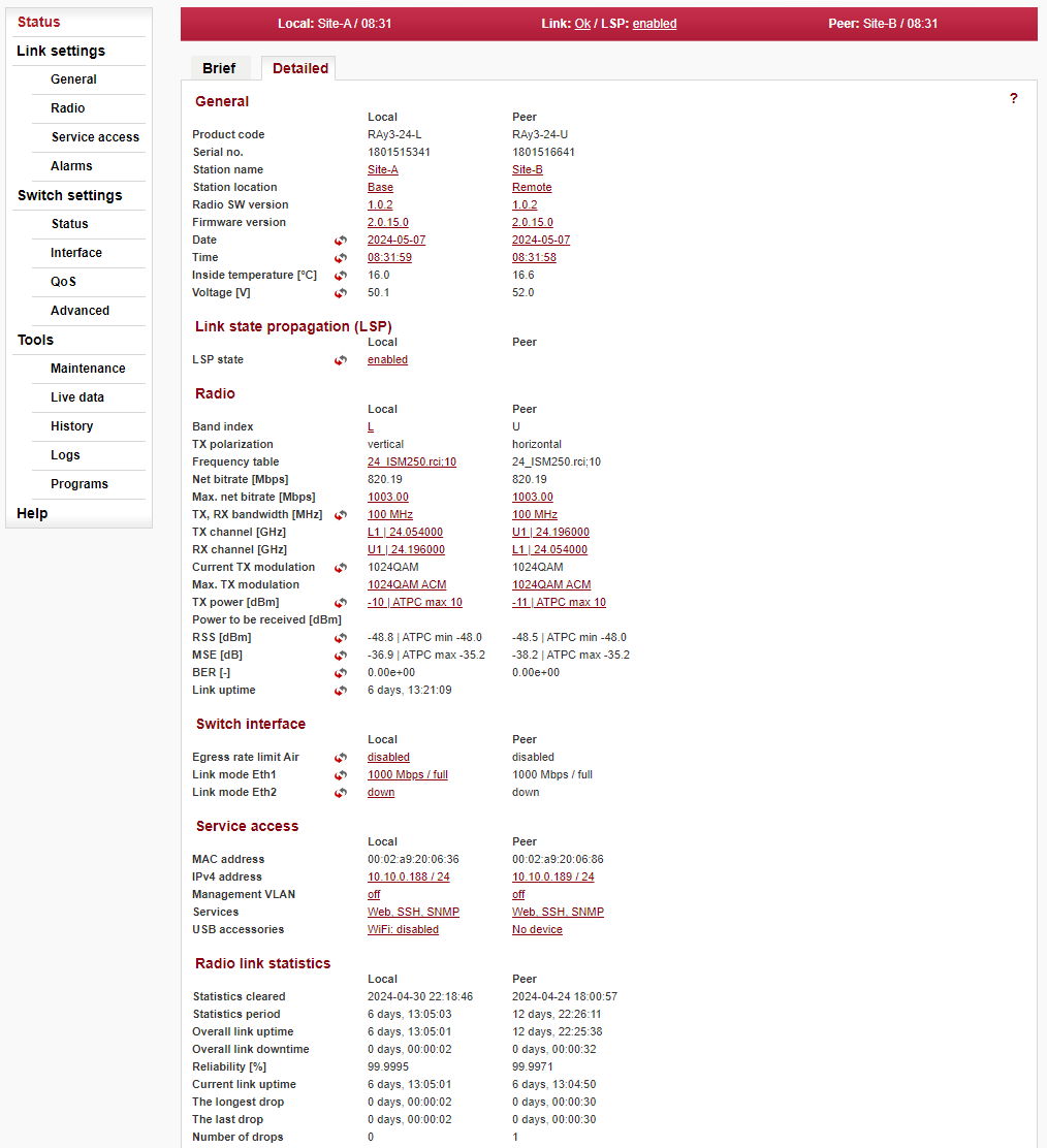
The ‘Status’ menu provides basic information about local and remote station. Information is valid in the moment, the page is opened, or the Refresh button is clicked. The ‘Status/Brief’ tab shows only the most important values whereas the ‘Status/Detailed’ tab provides further details.
Live status data
The ![]() icon marks fields which are automatically updated with 1 sec period when
the ‘Start’ button is active.
icon marks fields which are automatically updated with 1 sec period when
the ‘Start’ button is active.
LED indicator
System status is also indicated
by hardware LED indicator located below the semi-transparent plug on the housing of the FOD
unit, see Section 1.5, “Status LED ( S )”.
Below is a list of all values according both tabs ‘Brief’ and ‘Detailed’.
- General
- Product code
Unit product code – is the same as the Ordering code.
- Serial no.
Unit serial number.
- Station name
Station name can be modified by user (for example to reflect the unit location in the network topology).
- Station location
Station location (for example GPS position or to reflect the network topology hierarchy).
- Radio SW version
Software defined radio version.
- Firmware version
Unit’s firmware version.
- Date, Time
The internal real-time clock. The clock is set manually or it is synchronized with NTP server and set for both units.
- Inside temperature [°C]
Temperature inside the unit (on the modem board).
- Voltage [V]
Unit’s power supply voltage level.
- Link State Propagation (LSP)
- LSP state
The status of the LSP function can take on one of the following values:
disabled – LSP is not enabled
enabled – LSP is enabled but not active
activated – LSP is activated because the activation conditions have been met.
- Radio
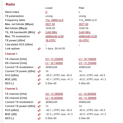
- Dual channel
In the case of Dual channel operation, the parameters of both channels are displayed in a separate section.
- Band index
Radio unit type: L (Lower) or U (Upper) part of the frequency band.
- TX polarization
Horizontal or vertical polarization based on the physical installation. Indicates the polarization of the transmitted signal. Local and Peer are indicated separately. The proper position of the cable is sideways down.
Notice for links in 17 GHz and 24 GHz bands: One side of the link must be installed in vertical polarization and the other in horizontal polarization.- Frequency table
Displays the currently used frequency table in format <name:version>.
- Net bitrate [Mb/s]
Current transfer capacity of radio channel for user data (Ethernet L1 capacity for packets 1518 bytes long).
- Max. net bitrate [Mb/s]
The maximum radio channel capacity according to installed SW key.
- TX, RX bandwidth [MHz]
The selected channel bandwidth for transmission and receive. For symmetrical links only one value is listed (i.e. local TX bandwidth = local RX bandwidth). For asymmetrical links both bandwidths are listed in format: ‘local TX bandwidth’ | ‘local RX bandwidth’.
- TX and RX channel [GHz]
Used channels. Both number of the channel and frequency in GHz are listed.
- Current TX modulation
Modulation currently used for transmitting.
- Max. TX modulation
Maximum permitted modulation (user defined upper limit for ACM/ACMB). When adaptive modulation is enabled (i.e. the parameter ‘ACM/ACMB min TX modulation’ is lower than ‘ACM/ACMB max TX modulation’), than the ACM/ACMB indication is displayed as well.
![[Note]](/images/radost/images/icons/note.png)
Note This parameter is displayed in FW 2.0.9.0 and previous just after the value of the current TX modulation (in the same row, separated by a slash).
- TX power [dBm]
Set power/maximum power when ATPC is turned on.
- Current TX power [dBm]
Current RF Output power on the TX channel in dBm. If ATPC is enabled, the ATPC letters are displayed as well as information about maximum permitted power: ‘current TX power’ | ATPC max ‘maximum TX power’.
- Calculated RSS [dBm]
Optional parameter to store the expected value of RSS.
- RSS [dBm]
Received signal strength. If ATPC is enabled, the ATPC letters are displayed as well as information about threshold value for activation of power control loop: ‘current RSS’ | ATPC min ‘threshold RSS’.
- MSE [dB]
Mean Square Error (the inverse to often used SNR – Signal to Noise Ratio). If ATPC is enabled, the ATPC letters are displayed as well as information about threshold value for activation of power control loop: ‘current MSE’ | ATPC max ‘threshold MSE’.
- BER [-]
Bit Error Rate is registered at the receiving end; instantaneous value.
- Link uptime
Time elapsed since the current link connection has been established.
- Switch interface
- Egress rate limit Air
Status of the Egress rate limiter on the Air interface. The traffic can be limited according to bits per second or frames per second.
Message format for bits per second: “xx.xx Mb/s Ly auto” where:
xx.xx Mb/s — Egress speed limit.
Ly — L1/L2/L3 which Ethernet layer is used for speed calculation.
auto — gives information about active Speed guard function.
Message format for frames per second: “xx.xx fps” where:
xx.xx fps — Egress frames per second limit.
- Link mode Eth1, Eth2
Status of Ethernet interface. Current bit rate:
10 = 10BASE-T
100 = 100BASE-TX
1000 = 1000BASE-T; 1000BASE-SX; 1000BASE-LX
2500 = 2.5GBASE-T
5000 = 5GBASE-T
10000 = 10GBASE-T; 10GBASE-SX; 10GBASE-LX
and state of duplex:
FD = full duplex
HD = half duplex
- Service access
- MAC address
HW address of the Ethernet module.
- IPv4 address
IP address in the standard dotted decimal notation, including the bit width of netmask after the forward slash.
- Management VLAN
Service access via VLAN management only.
- Services
Services enabled for unit management and monitoring (Web, Telnet, SSH, SNMP, NTP).
- USB accessories
Indicates physical devices inside USB connector in system slot ‘S’ and its status, for example:
n/a – info not available (peer has older fw),
No device – unplugged,
(Product) – not a network device,
WiFi: disabled,
WiFi: 169.254.170.168 / 28,
Eth: disabled,
Eth: 169.254.170.168 / 28
- Unit 24S compatibility
(formerly ‘Unit S mode’) This parameter is available only for newly deployed 24 GHz units without the ‘S’ label in Product code (i.e. ’24S’). When “active”, the unit behaves like the unit ’24S’ (it can establish a link only with another ’24S’ unit). For a link between the units without the ‘S’ label, this compatibility needs to be disabled (“off”).
- Radio link statistics
- Statistics Cleared
Time of log clearing.
- Statistics Period
Period of log refresh.
- Overall Link Uptime
Overall time the link has been connected.
- Overall Link Downtime
Overall time the link has been disconnected.
- Reliability [%]
The ratio of “Uptime” and “Downtime”.
- Current Link Uptime
Current time the link has been connected.
- The Longest Drop
The longest downtime period recorded.
- The Last Drop
Length of the last link interruption.
- Number of Drops
Number of link interruptions.
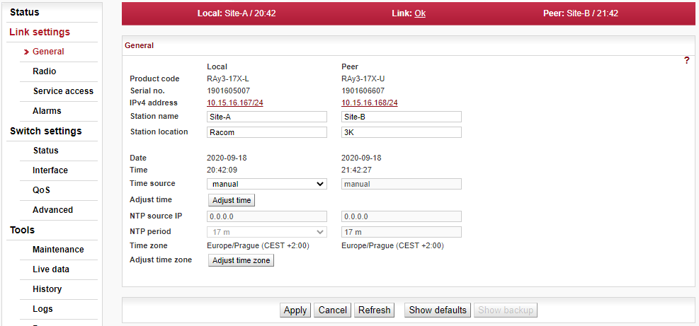
Setup of general parameters of the link.
- Product code
Unit type indicator.
- Serial no.
Unit serial number.
- IPv4 address
IP address in the standard dotted decimal notation, including the bit width of netmask after the forward slash.
- Station name
Station name can be modified by user (for example to reflect the unit location in the network topology).
- Station location
Station location can be modified by user (for example to reflect the network topology hierarchy).
- Date, Time
The internal real-time clock. The clock is set manually or it is synchronized with NTP server and set for both units.
- Time source
Time synchronization source setup. Manual setup or NTP protocol use. For easier diagnostics of link operation, it is recommended to use the NTP time synchronization.
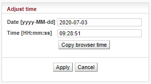
- Adjust time
Manual time setup. Use the dialog box to manually set the current date and time. You can copy time from browser (local PC).
- NTP source IP
IP address of the time synchronization server.
- NTP period
Time synchronization interval.
- Time zone
Unit Time zone in the format <Configured time zone> (<Used time zone code> <time offset>) ie.: “Europe/Prague (CEST +2:00)”.
Note When the time zone is changed, the original values set in the unit are kept. The actual change takes place after OS restart in order to prevent unexpected states related with local time change.
- Adjust time zone
Use the dialog box to set the new time zone. You can copy the time zone from a browser (local PC), select the time zone code from a list or input time zone string.
The string can be either time zone code from IANA time zone database (ie.: “Europe/Prague”) or the POSIX format (ie.: “CET-01:00:00CEST-02:00:00,M3.5.0/02:00:00,M10.5.0/03:00:00”). The posix format allows shortened variants usage when default values are used (ie.: “CET”, “CET-1CEST”, …).
The unit will reboot to use the new setting.
Setup of general parameters of the radio link.
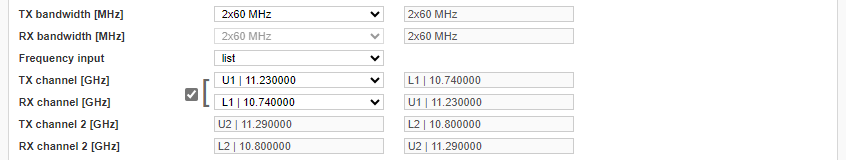
Some models of the RAy3 series (RAy3-11) allow to increase the transmission capacity by operating simultaneously in two radio channels. The setting of the second channel must meet the following conditions: both channels have the same bandwidth; both channels are adjacent to each other (Adjacent channels). The second channel is activated by selecting the Dual channel value in the TX bandwidth [MHz], RX bandwidth [MHz] parameter – example for two 112 MHz wide channels: “2x 112 MHz” The parameters of the transmission path can be slightly different for both channels, therefore the measurement of RSS, MSE and BER is separate for each channel. Similarly, ACM and ATPC work independently in each channel. In the case of operation in two channels, some radio parameters may differ compared to operation in one channel (lower value of max. available Tx power, lower sensitivity in some cases).
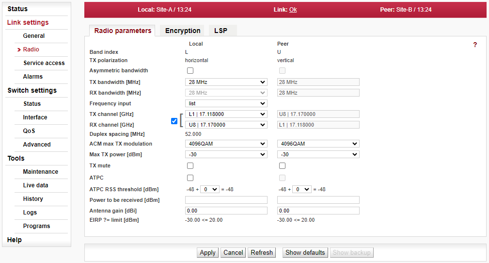
- Band index
Radio unit type: L(ower) or U(pper) part of the frequency band.
- TX polarization
Horizontal or vertical polarization based on the physical installation. Indicates the polarization of the transmitted signal. Local and Peer are indicated separately. The proper position of the cable is sideways down.
Notice for links in 17 GHz and 24 GHz bands: One side of the link must be installed in vertical polarization and the other in horizontal polarization.- Asymmetric bandwidth
Enables asymmetric channel bandwidth (only in models/bands where Asymmetry is supported).
- TX bandwidth [MHz], RX bandwidth [MHz]
One of the standard channel widths can be selected. This parameter must be set identically in local and remote (local TX bandwidth = peer RX bandwidth and local RX bandwidth = peer TX bandwidth). When units are connected, this is ensured automatically. If asymmetry is not allowed, then TX bandwidth = RX bandwidth on both units.
- Dual channel
If Dual channel operation is selected (by setting the TX bandwidth [MHz], RX bandwidth [MHz] parameter to a Dual channel value), the setting of the second channel becomes visible. The setting of the second channel is visible only for checking – the working frequency value is set automatically according to the frequency of the first channel and the selected bandwidth.
- Frequency input
Allows to choose if TX and RX channel frequencies are selected from the list of predefined channels or if manual input of frequencies would be possible (if supported).
- TX channel [GHz], RX channel [GHz]
TX and RX channels are selected from a list of channels. The basic configuration has the TX and RX options interconnected. In this case the basic duplex spacing between channels is preserved and by selecting one channel, the other three are defined as well. For units operating in free bands, it is possible to disconnect the TX-RX lock and select TX and RX channels individually. Corresponding channels at peer unit are set automatically (as long as the link to the other unit is established).
Note Non-standard duplex setting may lead to non-effective use of the spectrum. We recommend to use non-standard duplex spacing only in the situations when standard duplex spacing does not allow to establish the link.
- Duplex spacing [MHz]
Information about duplex spacing of currently selected TX and RX channel.
- ACM/ACMB max TX modulation
Upper limit of the ACM (Adaptive Coding and Modulation) or ACMB (Adaptive Coding, Modulation and Bandwidth) algorithm. Select lower than highest available modulation if the link speed fluctuation needs to be prevented. Select the same value for maximal and for minimal TX modulation if the link speed needs to be constant. The high order modulations may not be available for the narrowest and for the widest channel bandwidths.
Note The principle behind ACM and ACMB is to maintain the connection between the two units even when degraded propagation conditions are experienced which make it impossible to maintain the selected modulation level. ACM/ACMB regulates TX modulation across all ranges from ‘ACM/ACMB min TX modulation’ up to ‘ACM/ACMB max TX modulation’ (as configured by the user) according to the limits in table ‘ACM/ACMB switching according to MSE state’ (tables are specific for each frequency band – i.e. 10 GHz, 11/18 GHz, 17/24 GHz, 80 GHz).
ACM/ACMB control loop is evaluated with each frame, i.e. roughly after tens of microseconds.- Max TX power [dBm]
Maximum allowed level of RF output power. The value is limited by technical parameters of the unit. The maximum selectable value differs for various HW options, various modulations and can be affected by a (non)installed SW feature key for full TX power.
Note Only for 80 GHz units: When ACMB shifts the modulation down (due to the weather or other factors), the TX power limit is automatically increased up to the highest available TX power for the new modulation limited by the configured value of ‘Max TX power’ (lower value applies). ATPC operates up to this TX power limit.
- TX mute
Mutes TX transmission for unlimited time (until this setting is manually de-activated). The link transmission will be interrupted by applying this setting.
![[Important]](/images/radost/images/icons/important.png)
Important It would not be possible to de-activate ‘TX mute’ on Peer unit from the Local one, because the communication between both units will be non-operational due to TX muted on Peer unit. Thus some other network connection to the Peer unit would be required to de-activate this setting. (If such an alternative route does not exist, a site visit will be necessary).
- ATPC
Enables automatic control of RF power. Once enabled, the RF Output power is regulated towards lower level while maintaining signal level high enough not to affect current degree of modulation. Its maximum is defined by parameter ‘Max TX power’ and by the technical parameters of the unit for the currently active modulation.
Note The principle behind ATPC is to maintain the lowest transmitting power without affecting the throughput of the link. The output is primarily controlled by RSS on the opposite side. ATPC is also used to maintain MSE thus protecting the selected modulation level.
The ATPC Control loop is evaluated once per second.In normal operating conditions, ATPC is applied first (even if it is the slower control loop). When deterioration in propagation conditions gradually increases the attenuation on the route, it is compensated by increasing RF power. ACM/ACMB control will only be applied in conditions when ATPC reaches its ceiling.
- ATPC RSS threshold [dBm]
Comparison RSS with this threshold is used for signaling to the peer ATPC algorithm to adjust RF power. The lowest allowed RSS (the threshold) is approx. 10 dBm above declared sensitivity for BER 10-6. If necessary, use this parameter to move the threshold slightly up or down.
- Calculated RSS [dBm]
Optional parameter to store the expected value of RSS
- Antenna gain [dBi]
Valid only for 17 GHz and 24 GHz links. Gain of used antenna. It is used to calculate approximate EIRP.
- EIRP ?= limit [dBm]
Valid only for 17 GHz and 24 GHz links. Approximate calculation of EIRP. Number on the right shows the allowed EIRP limit (in most countries it is 20 dBm). Sign between numbers gives information on compliance / noncompliance with allowed EIRP limits.
| Note | |
|---|---|
If you enter radio link parameters which interrupt the connection on an operating link, the original parameters will be automatically restored after 1 minute (see Section 5.1.5, “Rollback function”). The only exception is during activated ‘TX mute’, which disconnects the link permanently (until ‘TX mute’ is manually de-activated). |
This functionality requires the encryption activation SW key to be installed in both units (available for all bands except 80 GHz). Once installed, part of the user data traffic (one Ethernet port) can be AES encrypted to ensure the security of the over the-air communication.
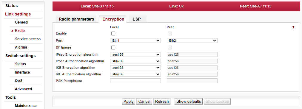
IPsec VPN tunnel by Security Association with symmetrical cryptography is used to encrypt the packets and to ensure keys are safely delivered to the peer and regularly exchanged.
The protocol used for secure key exchange is IKE (Internet Key Exchange) version 2.
Link partner (peer) secure authentication is assured using Pre-Shared Key (PSK) authentication. Both link partners share the same key (password).
The other (non-encrypted) Ethernet port can be used simultaneously with the encrypted port for data transfer and/or for the unit management. The link capacity in the air is shared by both Ethernet ports. The encrypted traffic has a higher priority.
- Enable
When user data encryption is enabled, the IPsec tunnel is started.
- Port
The Encryption service encrypts all the user data traffic originating from one of two Ethernet ports. Ethernet port Eth1 or Eth2 needs to be selected. It is possible to select different Ethernet ports on each side of the link (e.g. Eth1 on Local and Eth2 on Peer).
- DF Ignore
If the communication over the given Ethernet port is encrypted, the longest packet passing through without fragmentation are 2048 Bytes long. The longer packets need to be fragmented:
in the previous network device, or
the DF (Do-Not-Fragment) bit in the incoming packets must be cleared, or
the DF Ignore bit needs to be set
Packets longer than 9000 Bytes are discarded.
- IPsec Encryption algorithm
IPsec SA encryption algorithm. The stronger the algorithm, the lower the user data throughput.
- IPsec Authentication algorithm
IPsec SA integrity algorithm. The stronger the algorithm, the lower the user data throughput.
- IKE Encryption algorithm
IKE SA encryption algorithm.
- IKE Authentication algorithm
IKE SA integrity algorithm.
- PSK Passphrase
PSK (Pre-shared key) authentication is used for IKE SA authentication. The key must be the same for both Local and Peer units.
| Note | |
|---|---|
PIRL setup
recommendation This functionality requires the encryption activation SW key to be installed in both units.
|
LSP allows the unit or the entire link to automatically respond to reduced radio channel throughput. Communication between units is maintained even if the LSP function is activated (provided the received signal level is above the most robust modulation sensitivity). Various LSP actions can be triggered when LSP is activated. Access to the remote unit is possible via port forwarding of the local unit (ports allowed are: 8022, 8023, 8080, 8161 and 8443).
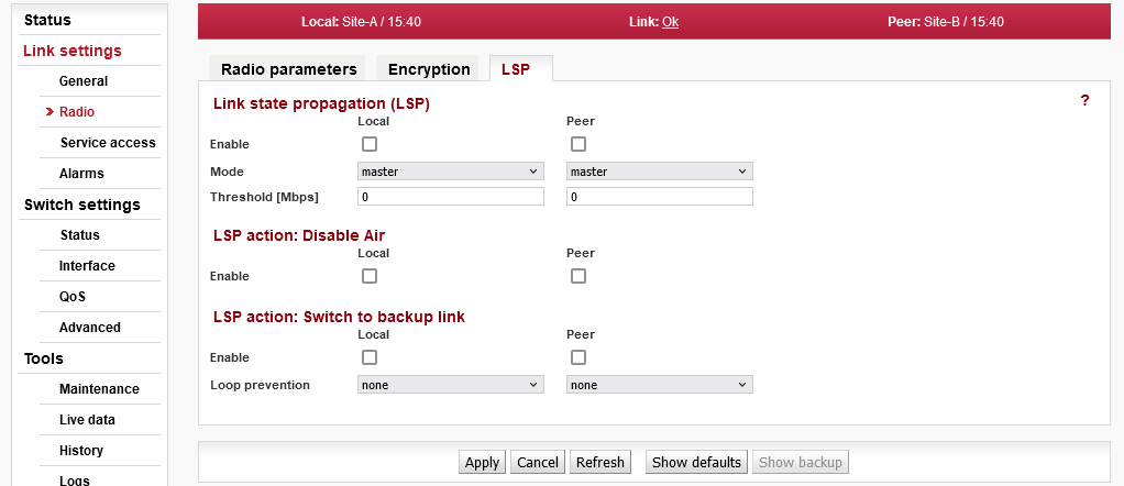
Link State Propagation (LSP)
- Enable
Enables LSP on the corresponding unit.
- Mode
Master: activates the LSP function depending on the link speed (radio channel throughput) of this unit. See the description of the Threshold parameter.
Slave: If the link is connected, it activates the LSP function synchronously with the activation of this function on the Peer unit.
If the link is disconnected, it activates the LSP function depending on the current link speed, i.e. the same as when selecting Master mode.- Threshold [Mbps]
User speed threshold for activating the LSP function. When the current “Net bitrate” value drops below the set threshold, LSP is activated. “0” means function is disabled.
Actions:
Depending on the network configuration, one of the following actions can be selected when the LSP function is activated:
LSP action: Disable Air
- Enable
Deactivates the connection of the ETH1 and ETH2 ports to the AIR port, which prevents the transmission of user data via the microwave link.
LSP action: Switch to backup link
- Enable
Deactivates the connection of the ETH1 and ETH2 ports to the AIR port and connects the ETH1 and ETH2 ports. Thus, user data will not be transmitted over the air, but sent to the second ETH port, where a backup connection is assumed.
- Loop prevention
Selects a port that is not connected to the AIR port to avoid an Ethernet loop.
LSP action: Port shutdown
- Enable
Switches the ETH port to “link down” when LSP is activated. PoE power remains active. If the port is down, it is not even possible to access the management of the device from this port.
- Port
Selecting a port to “link down” when LSP is activated..
Ongoing Development of LSP (Link State Propagation) Functionality
We are continually refining the functionality of the LSP (Link State Propagation) feature to enhance your overall user experience. As part of this ongoing development process, it is crucial to acknowledge that the LSP function is still in the refinement stage.
Pre-Deployment Testing Recommendations
Examples of functional configurations can be found in the APP note, which can be found in the Application Notes section of the manufacturer’s website.
Prior to implementing the LSP feature in a live environment, we strongly advise conducting thorough testing in a controlled laboratory setting. This step ensures that the LSP functionality aligns seamlessly with your specific requirements and minimizes the risk of network loops.
Testing Guidelines:
Validate that the LSP function operates in accordance with your specified configuration.
Verify that the LSP does not induce any unintended network loops or disruptions.
Ensure that the LSP performs reliably under diverse network conditions and scenarios.
Your feedback during this testing phase is invaluable in helping us deliver a robust and dependable solution tailored to your needs.
We welcome any feedback or questions you may have during the testing process. Your input is instrumental in our commitment to providing the highest quality of service.
Access routes for link configuration.
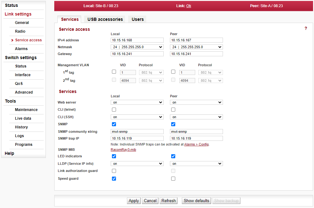
Service access
- IPv4 address
Service IP address, by default 192.168.169.169 for L unit and 192.168.169.170 for U unit. Management address of the Peer station has to be set up as well.
Note Unknown IP address
If you forget the Service IPv4 address, it can be found by reading data broadcast through LLDP protocol. Data is transmitted every 60 seconds and contains the following information:1. Management address: IP address
2. System Description: Serial number
3. Chassis Subtype: Unit product type
4. IEEE 802.1 – Port and Protocol VLAN ID: Port and Protocol VLAN Identifier: (e.g. 300 (0x012C)) but only if Management VLAN is enabled
The message can be recorded and converted into a readable form using an LLDP client. A suitable tool for this purpose is Wireshark IP traffic analyzing tool, with free licenses available for both Windows and Linux. To locate the message easily, use the Capture filter “ether proto 0x88cc” in Wireshark.
- Netmask
Mask for service access, 24 by default.
- Gateway
Default gateway for service access; empty by default.
- Management VLAN, 1st tag, 2nd tag
Enables management access via VLAN. Management VLAN can be single-tagged or dual-tagged. Line for 2nd tag gets active only after 1st tag is activated. Blocks access for HTTPS, ssh and telnet configuration via untagged packets (without VLAN) making only VLAN access possible. VLAN management is off by default.
![[Warning]](/images/radost/images/icons/warning.png)
Warning By enabling VLAN management, ALL accesses are blocked for configuration using normal (untagged) LAN! During tests, you may enable VLAN management on one unit only. Then it is possible to access the link via LAN and VLAN either directly or via radio link.
- VID
VLAN management ID, by default 1. This field must have a value entered even when VLAN management is not active.
- Protocol
Protocol 802.1q or 802.1ad
Services
- Web server
Allows access via web server (for HTTP and HTTPS protocol).
Warning After disabling access via web server, you will not be able to access the unit using a web browser!
- CLI (telnet)
Enables access via telnet protocol. Provides access to CLI (Command Line Interface) for simple telnet clients. Disabled by default.
- CLI (SSH)
Enables access via SSH protocol. Provides secure access to CLI. If preventing unauthorized access to the unit is the number one priority, leave only this server on.
- Technical support access
If security policies require it, this parameter can be used to completely disable access to the internal root maintenance account.
- SNMP
Enabling SNMP server. Off by default.
- SNMP community string
SNMP community string. Can contain both lower and uppercase letters, numbers, four characters . : _ – and can be up to 256 characters long.
- SNMP trap IP
Address for sending SNMP traps. It is possible to record up to 3 addresses separated by commas.
- SNMP MIB
Saving a file with SNMP MIB (Management Information Base) table. The downloaded file is identical to the SNMP MIB table file downloaded from web (section Downloads) for relevant FW version.
- LED indicators
Enable LED status indicators on the body of the unit. You can turn off LED indication with this option.
- LLDP (Service IP info)
Data transmitted through the LLDP protocol can be accessed in two ways:
OnTransmissions every 60 seconds
SingleTransmitted once only when unit is rebooted
See “IPv4 address – Local … Unknown IP address” for description of the data transmitted through the LLDP protocol.
- Link authorization guard
User data flow to the remote unit can be established dependent on remote station authorization. The authorization is secured by using SSH keys. For info about unit authorization see user manual, section CLI > Configuration with CLI > Remote unit authorization.
Disabled — User data flow through the Air channel is enabled even if the remote unit is not authorized.
Enabled — User data flow through the Air channel is enabled only if the remote unit is authorized. The “Link authorization guard” parameter value of the remote unit is ignored.
- Speed guard
The speed guard controls automatically the Egress data rate shaping according to available capacity of the Air channel. The Air channel capacity check and the Egress shaping adjustment takes place approx. once per 50 ms.
- SyncE source
The port that will be used as the frequency source for Synchronous Ethernet.
The USB connector is used for management access (not for user data) to the local unit using Ethernet or WiFi adapter. Only adapters officially recommended by the unit vendor are supported.
Default WiFi IP address of the unit is 172.17.17.17 with DHCP enabled by default allocating IP address automatically to connected device.
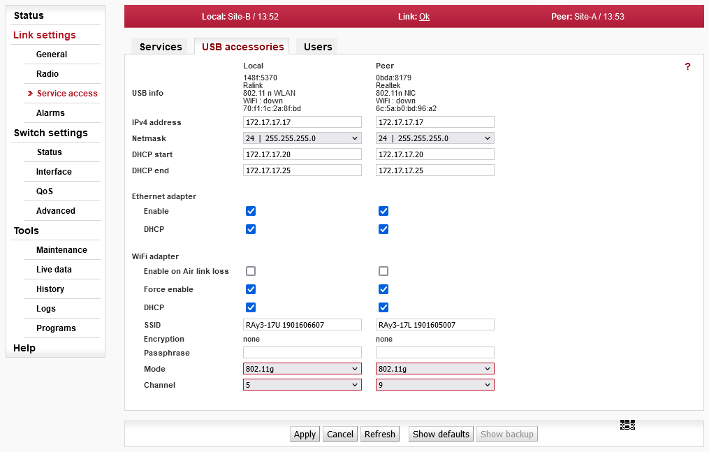
- USB info
Status information about device connected via the USB:
n/a – info not available (HW in USB slot not recognized by FW = probably not officially supplied accessory), or
No device – no device plugged in the USB port, or
List of basic USB module credentials:
Vendor ID: Product ID
Manufacturer
Product
WiFi/Eth: up/down — only for network device
MAC — only for network device
- IPv4 address
Unit service management address when connecting via USB port.
- Netmask
Network mask when connecting via USB port.
- DHCP start
DHCP range for dynamic address allocation of the management client connected via USB port.
- DHCP end
DHCP range for dynamic address allocation of the management client connected via USB port.
- Ethernet adapter Enable
Enables operation of USB/Eth adapter.
- Ethernet adapter DHCP
Enables DHCP for the client(s) connected via USB Ethernet adapter.
- WiFi adapter Enable on Air link loss
WiFi is activated only during Air-Link loss – means WiFi starts to work and transmit SSID. WiFi is activated 60 seconds after Air-Link loss and deactivated 600 seconds after the Air-Link is restored. The WiFi passphrase should be set by admin before using this option (if not WiFi management alarm is activated).
- WiFi adapter Force enable
WiFi is forced to be permanently active (and to transmit SSID) and WiFi management alarm is activated. WiFi passphrase should be set by admin before using this option.
This parameter has a higher priority than “WiFi adapter enable on Air link loss”, so if it is set ON then WiFi activity does not depend on Air-Link status.
- WiFi adapter DHCP
Enables DHCP on WiFi adapter if present (for automatic setting of client(s) IP address).
- WiFi SSID
Name of service WiFi visible by clients (can be max. 32 characters long).
- WiFi Encryption
Service WiFi encryption is WPA2 and cannot be changed. Factory default is “none” due to missing passphrase. WPA2 is applied automatically once any passphrase is entered.
- WiFi Passphrase
Service WiFi passphrase has to be 8-64 characters long. The WiFi passphrase should be set by admin before any use of WiFi. Until passphrase is set, WiFi management alarm is activated.
- WiFi Mode
Service WiFi mode can be IEEE 802.11n or IEEE 802.11g
- WiFi Channel
WiFi channel can be set 1-11 depending on WiFi mode setting (see parameter above):
IEEE 802.11n — channels 1-7
IEEE 802.11g — channels 1-11
The WiFi adapter does not search for conflicts in the air. If problems occur, changing the channel is the easiest way to resolve the issue.
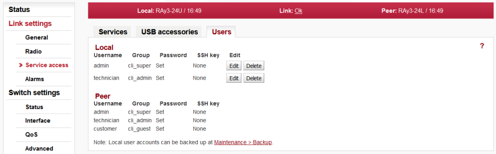
List and setup of users. Example menu of the cli_super level user.
When logging in for the first time, the user is prompted to enter a username and
password, to this user is assigned the highest level of permissions
cli_super. This user then assigns other users to the system along with their
level of permissions.
Service access has three groups of users with different levels of permissions.
| Permissions | cli_guest | cli_admin | cli_super |
| Create new user | No | No | Yes |
| Change own password | Yes | Yes | Yes |
| Delete user * | No | No | Yes |
| Copy (Mirror) permissions local to peer | No | No | Yes |
| Configure and modify link settings | No | Yes | Yes |
Numbers of users that can be defined in the system:
| Group | No of users |
| cli_guest | 10 |
| cli_admin | 10 |
| cli_super * | 2 |
* The system prevents the user from deleting both
cli_super accounts.
The logged-on user is shown in the top right of the screen. There can be different users on either end of the link.
| Important | |
|---|---|
Using the CLI, it is appropriate to supplement the SSH key. |
Local, Peer
List of users on Local and Peer stations.
- Username
This name is entered at Login to log into the link management.
- Group
User group to which the user belongs.
cli_guest – Read Only
cli_admin – Configure and modify link settings
cli_super – Configure and modify user accounts and link settings
- Password
Information about whether user has a password
- SSH key
Information about whether user has at least one ssh key defined.
| Note | |
|---|---|
More users concurrently |
Edit user
Clicking “Edit” next to a username opens a screen with configuration of the given account.
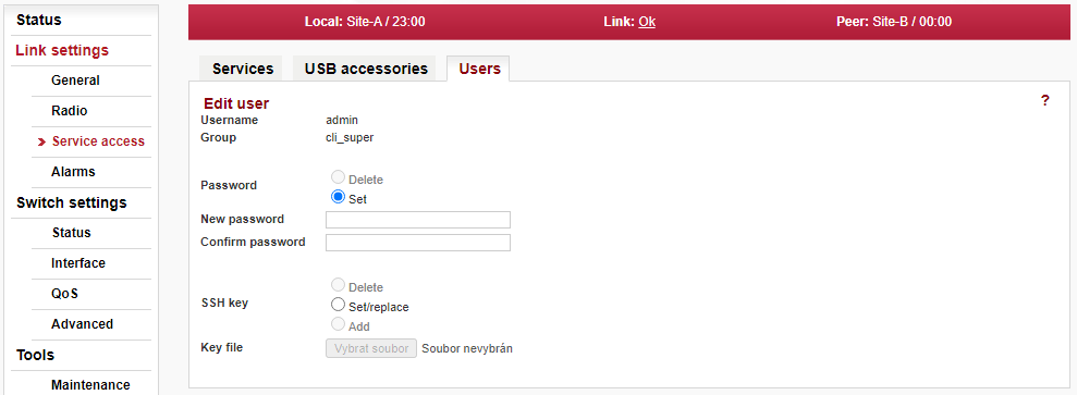
- Username
User name.
- Group
The group to which this user will belong.
- Password
Password can be set or deleted.
– User will not have a password. The user will only be able to log in with a ssh key. In order to delete the password, you must first upload the ssh key.
– Password settings
- New password
New password.
- Confirm password
Repeat password.
- SSH key
Working with ssh key.
– Clear all ssh keys from user account.
– Add a new key. If there already was any key(s), it will be overwritten.
– Add a new key. You can enter multiple ssh keys in this way.
- Key file
Insert key file.
Save the menu content by clicking on the button Apply.
| Note | |
|---|---|
The user settings can be backed up, see Tools > Maintenance > Backup. |
Delete user
Users at level cli_super have a Delete button next to each user. Delete a
user using this button without being asked to confirm deletion. Users at level
cli_super cannot both be deleted.
Add user
The button is located on the bottom bar.
For level cli_super users, the “Add user” button is active. Use it to
create a new user within any group.
- Username
Name of new user.
- Group
The group to which this user is assigned.
- New password
Password for this user.
- Confirm password
Repeat password.
- SSH key
If you want the user to have access using ssh protocol and identity verification using ssh key, enter the ssh key here.
Create a new user account by clicking on the button Apply.
Mirror users
The button is located on the bottom bar.
For level cli_super users, the “Mirror users” button is active. This
function will copy all user accounts from Local unit to Peer unit. All existing user
accounts on the Peer unit are deleted.
Overview of alarms
| alarm | ||
| warning | ||
| cleared / OK | ||
| ✓ | confirmed |
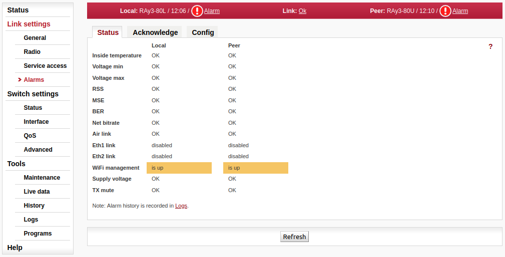
All system alarms are listed on this screen. Inactive alarms are colored white with an “OK” text label. Active alarms are colored according to the severity of the alarm with a text message describing the measured value status.
For a detailed description of each Alarm see Section 5.4.4.3, “Alarms Config”, in unit management just click on the Alarm name.
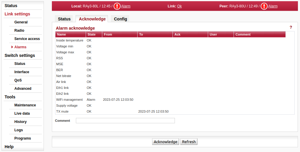
Alarm acknowledgement allows the operator to confirm the system is set in alarm state. Only an active alarm can be acknowledged. Multiple selections of active alarms (to acknowledge groups of alarms) can be performed using Shift or Ctrl keys.
- Name
Alarm identification – The following alarms can appear: Inside temperature, Voltage min, Voltage max, RSS, MSE, BER, Net bitrate, Air link, Eth1 link, Eth2 link, RF power, WiFi management
- State
There are three possible alarm states:
OK — No alarm (alarm is inactive) or alarm disabled.
Ack — Alarm is active and acknowledged.
Alarm — Alarm is active and is not acknowledged.
- From
Time stamp when the alarm occurred.
- To
Time stamp when the alarm expired (returned to normal conditions).
- Ack
Time stamp when the alarm was acknowledged. Time stamp format: yyyy-MM-dd hh:mm:ss
- User
Name (login) of the user who acknowledged the alarm.
- Comment
The comment field can be used to add user defined comments when an ‘alarm acknowledge’ is performed. Use this comment field to describe important details of the alarm status. The comment can be up to 50 characters long. Special characters are not allowed. The alarm can be acknowledged multiple times with different comments. Every acknowledgement is written to the internal memory and is visible in the alarm log.
The diagnostics system of the link monitors the operation of both units.
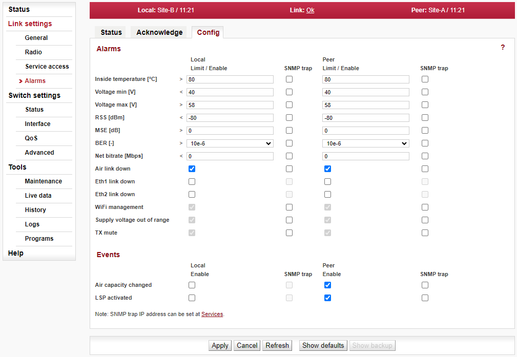
It generates various event outputs – system warnings and alarms. The event is always written to the system log and indicated in the Status bar and Alarms/Status screen. Some events have adjustable thresholds. Events with no adjustable thresholds may or may not be Enabled. If they are not Enabled, the system event is not activated even if the system status is changed.
If the event goes above or below the set parameter limits or a link goes down or up, you can choose to send an SNMP trap. All SNMP traps are OFF in defaults.
Alarms
- Inside temperature [°C]
Default >80; severity: alarm
Temperature inside the unit (on the modem board). Active if temperature exceeds the threshold.
- Voltage min [V]
Default <40; severity: alarm
Lower threshold of supply voltage. Active if voltage drops below min voltage threshold.
The same SNMP trap (same OID) applies for both Voltage min and max.
- Voltage max [V]
Default >58; severity: alarm
Upper threshold of supply voltage. Active if voltage rises above max. voltage threshold.
The same SNMP trap (same OID) applies for both Voltage min and max.
- RSS [dBm]
Default <-80; severity: alarm
Received Signal Strength. Active if RSS drops below RSS threshold.
- MSE [dB]
Default >0; severity: alarm
Mean Square Error (the inverse to often used SNR – Signal to Noise Ratio). Active if MSE rises above MSE threshold.
- BER [-]
Default >10e-6; severity: alarm
Bit Error Rate is registered at the receiving end of the link – instantaneous value. Active if BER exceeds the threshold set in this parameter.
- Net bitrate [Mb/s]
Default >0; severity: warning
The system warning is generated when the current transfer capacity of radio channel is lower than the threshold set in this parameter.
- Air link down
Default on; severity: alarm
Interruption of radio link. Active if radio link is interrupted and units can not communicate by Air.
- Eth1/Eth2 link down
Default off; severity: alarm
Corresponding user Eth link (Eth1/Eth2) on station interrupted.
Note The “EthX link” system alarm can only be activated if this alarm is Enabled. When the alarm is not Enabled, the “EthX link” alarm on Status screen is always “Ok” regardless of the current status of the Ethernet link.
- WiFi Management
Default on; severity: warning
Warning is generated when WiFi passphrase is not set or WiFi adapter (and Host Access Point) is permanently enabled (WiFi Force Enable is ON). Parameter can not be changed in web interface (only through CLI).
- Supply voltage out of range
(RAy3-18 and RAy3-80 only)
Default on; severity: alarm
Active if voltage before boot is outside of unit voltage range (printed on the unit Product label). Indicated also by the system status LED (no color).
Note The unit does not fully boot. Re-boot the unit by re-powering it with a proper power supply.
- TX mute
Default on; severity: warning
Alarms when TX transmission is muted by the operator (i.e. the radio link is out of operation due to the decision of the operator).
Events
- Air capacity changed
Default off
If allowed, the Event and/or SNMP Trap is generated when Net bitrate of the air channel changes (e.g. because of ACM/ACMB operation).
- LSP activated
Default off
If allowed, the Event and/or SNMP Trap is generated when LSP is activated (Link capacity drops bellow the preset threshold).
Ethernet switch is a key part of the unit. It is responsible for data transfer inside the unit – see Appendix C, Unit block diagrams.
The unit internal Ethernet switch port status
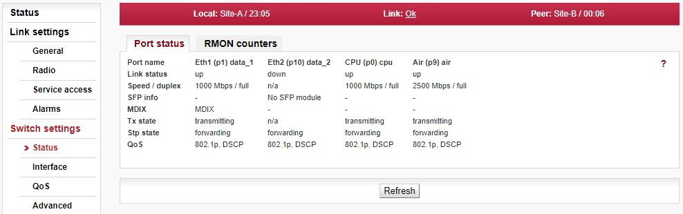
- Port name
Identification of the internal switch port. The switch ports are connected to an external port or to an internal device (radio modem, management CPU).
Eth1 (port1) — The external port (with RJ45 interface) labeled “ETH1+POE”.
Eth2 (port10) — The external port (with SFP interface) labeled “ETH2”.
CPU (port0) — The internal port to management CPU.
Air (port9) — The internal port to radio modem, i.e. link to the peer unit.
- Link status
Ethernet link status can be
down — no link signal detected
up — link signal detected
- Speed / duplex
Ethernet link Speed and duplex.
Speed: — 0/100/1000 Mb/s.
Duplex: — full/half
- SFP info
Information about the (optionally) inserted SFP module – see Section 1.3.2, “SFP/SFP+ slot (ETH2)” for info about available SFP modules. Four situations may appear:
SFP OK — The SFP vendor string read out of SFP module. The vendor, model, connector (RJ45/LC) and wavelength values are shown. Separate window with more detailed information can be opened by clicking the “more…” link.
No SFP module — SFP module not inserted
read error — SFP info can not be read
no SFP option — n/a
- MDIX
Status of the internal crossover of Ethernet cables. (MDIX = internally crossed pairs, MDI = direct connection, N/A means an unknown state).
- Tx state
Port transmitting status can be
transmitting — Normal port operation.
paused — Port transmitter is paused due to Pause frames reception.
n/a — Info not available.
- Stp state
Ethernet switch port forwarding control.
disabled — The switch port is disabled and it will not receive or transmit any frames.
forwarding — The switch examines all frames, learning source addresses (SA) from all good frames (except those from MGMT frames) and receives and transmits all frames as a normal switch.
blocking — Only MGMT frames are allowed to enter (ingress) or leave (egress) a Blocked port. All other frame types are discarded. Learning is disabled on Blocked ports.
learning — Only MGMT frames are allowed to enter (ingress) of leave (egress) a Learning port. All other frame types are discarded but learning takes place on all good non-MGMT frames that are not discarded owing to being filtered.
- QoS
Quality of Service status. It will be available starting from FW version 1.1.1.0. It can present one of the following values:
disabled — QoS functions are disabled.
802.1p — QoS according to 802.1p is enabled.
DSCP — QoS according to DSCP is enabled.
802.1p,DSCP — QoS according to 802.1p and DSCP is enabled. The 802.1 prefer tag is selected.
DSCP,802.1p — QoS according to 802.1p and DSCP is enabled. The DSCP prefer tag is selected.
The unit internal Ethernet switch RMON counters
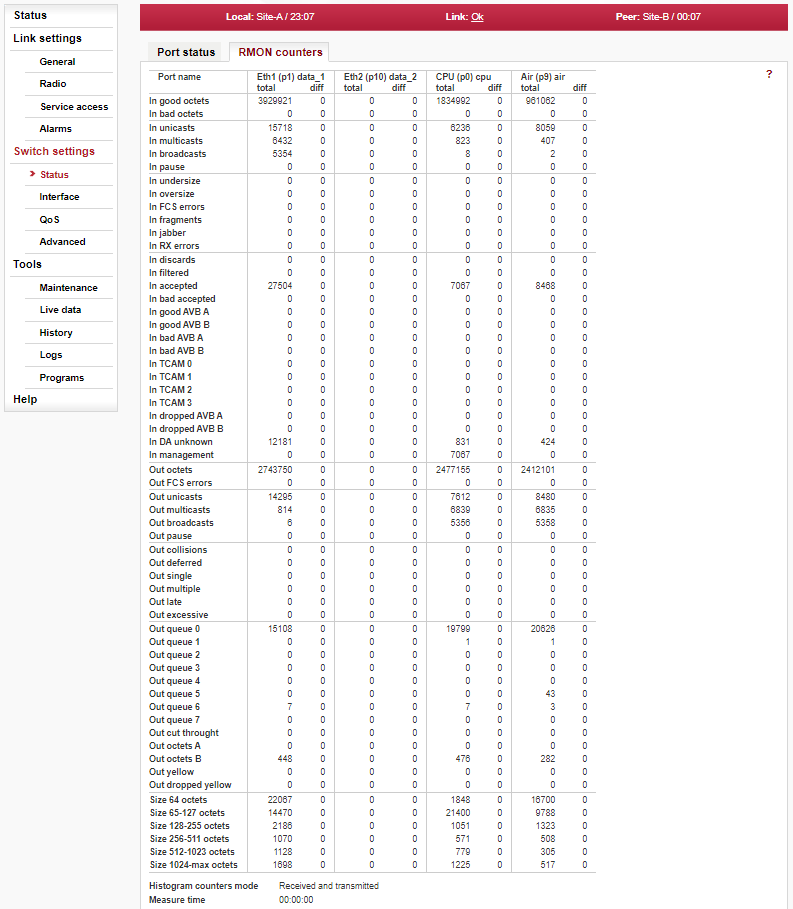
The Remote Network MONitoring (RMON) MIB was developed by the IETF to support monitoring and protocol analysis of LANs.
- Port name
Identification of the internal switch port. The switch ports are connected to an external port or to an internal device (radio modem, management CPU).
Eth1 (port1) — The external port (with RJ45 interface) labeled “ETH1+POE”.
Eth2 (port10) — The external port (with SFP interface) labeled “ETH2”.
CPU (port0) — The internal port to management CPU.
Air (port9) — The internal port to radio modem, i.e. link to the peer unit.
The Internal switch port RMON counters
These counters provide a set of Ethernet statistics for frames received on ingress and transmitted on egress.
Ingress statistics counters
- In good octets
The sum of lengths of all good Ethernet frames received, that is frames that are not bad frames.
- In bad octets
The sum of lengths of all bad Ethernet frames received. Fragments are included.
––––––––––––––––––
- In unicasts
The number of good frames received that have a Unicast destination MAC address.
- In multicasts
The number of good frames received that have a Multicast destination MAC address.
Note This does not include frames counted in “In broadcasts” nor does it include frames counted in “In pause”.
- In broadcasts
The number of good frames received that have a Broadcast destination MAC address.
- In pause
The number of good frames received that have a Pause destination MAC address (Flow Control frames). This includes Priority Flow Control Pause frames too.
––––––––––––––––––
- In undersize
Total frames received with a length of less than 64 octets but with a valid FCS.
- In oversize
Total frames received with a length of more than MaxSize octets but with a valid FCS.
- In FCS errors
Total frames received with a CRC error not counted in “In fragments”, “In jabber” or “In RX” errors.
- In fragments
Total frames received with a length of less than 64 octets and an invalid FCS.
- In jabber
Total frames received with a length of more than MaxSize octets but with an invalid FCS.
- In RX errors
Total frames received with an RxErr signal from the PHY.
––––––––––––––––––
- In discards
The number of good, non-filtered frames that are received but cannot be forwarded due to a lack of buffer memory.
- In filtered
The number of good frames that were not forwarded due to ingress policy filtering rules.
- In accepted
The number of good frames that are not policy filtered nor discarded due to an error and made it through the Ingress process and is presented to the Queue Controller.
- In bad accepted
The number of good frames that were not forwarded due to ingress policy filtering rules.
- In good AVB A, B
The number of good AVB frames received that have a Priority Code Point for Class A (or B) that are not Undersize nor Oversize and are not discarded or filtered.
- In bad AVB A, B
The number of bad AVB frames received that have a Priority Code Point for Class A (or B) that are not Undersize nor Oversize.
- In TCAM 0 … 3
The number of good frames received that have a TCAM Hit on a TCAM Entry that has its IncTcamCtr bit set to a one and its FlowID[7:6] = 0 … 3 and are not discarded or filtered. This allows this counter to be used for any purpose as programmed in the TCAM.
- In dropped AVB A, B
The number of good AVB frames received that have a Priority Code Point for Class A (or B) that are not Undersize nor Oversize and are not discarded or filtered but were not kept by the switch due to a lack of AVB buffer.
- In DA unknown
The number of good frames received that did not have a Destination Address ‘hit’ from the ATU (i.e., the frame’s DA was not in the address database) and are not discarded or filtered.
- In management
The number of good frames received that are considered to be Management frames and are not discarded (i.e., the frame’s size is legal and its CRC is good or it was forced good by register. Remote Management frames are counted regardless if the RMU accepted them or not.
Egress statistics counters
- Out octets
The sum of lengths of all Ethernet frames sent from this MAC.
- Out FCS errors
The number of frames transmitted with an invalid FCS. Whenever a frame is modified during transmission (e.g., to add Out FCS errors or remove a tag) the frame’s original FCS is inspected before a new FCS is added to a modified frame. If the original FCS is invalid, the new FCS is made invalid too and this counter is incremented.
––––––––––––––––––
- Out unicasts
The number of frames sent that have a Unicast destination MAC address.
- Out multicasts
The number of good frames sent that have a Multicast destination MAC address.
Note This does not include frames counted in “Out broadcasts” nor does it include frames counted in “Out pause”.
- Out broadcasts
The number of good frames sent that have a Broadcast destination MAC address.
- Out pause
The number of Flow Control frames sent. This includes Pause and Priority Flow Control frames.
––––––––––––––––––
- Out collisions
The number of collision events seen by the MAC not including those counted in “Out Single”, Multiple, Excessive, or Late. This counter is applicable in half-duplex only. See Auto negotiation.
- Out deferred
The total number of successfully transmitted frames that experienced no collisions but are delayed because the medium was Out deferred busy during the first attempt. This counter is applicable in halfduplex only.
- Out single
The total number of successfully transmitted frames that experienced exactly one collision. This counter is applicable in halfduplex only.
- Out multiple
The total number of successfully transmitted frames that experienced more than one collision. This counter is applicable in halfduplex only.
- Out late
The number of times a collision is detected later than 512 bitstimes into the transmission of a frame. This counter is applicable in half-duplex only.
- Out excessive
The number frames dropped in the transmit MAC because the frame experienced 16 consecutive collisions. This counter is applicable in half-duplex only.
––––––––––––––––––
- Out queue 0 … 7
The number of frames that egress this port from Queue 0 … 7. It does not matter if these frames had a good CRC or not.
- Out cut through
The number of frames that egress this port from the Cut Through path. It does not matter if these frames had a good CRC or not nor what the frame’s size was.
- Out octets A, B
The sum of lengths of all Ethernet frames sent from the AVB Class A (or B) Queue not including frames that are considered Out octets A, B Management by Ingress. The purpose of this counter is to measure the actual used rate of the shaper for stream data. The actual data rate from any queue, AVB or not, can be measured with this counter, however.
- Out yellow
The number of Yellow frames that egressed this port (i.e., the number of Yellow frames that successfully made it through the queue controller).
- Out dropped yellow
The number of Yellow frames not counted in “In discards” that are ‘head dropped’ from an egress port’s queues and the number Out dropped yellow of Yellow frame’s ‘tail dropped’ from an egress port’s queues due to Queue Controller’s queue limits.
Frame size histogram counters
- Size 64 octets
Total frames received (and/or transmitted) with a length of exactly 64 octets, including those with errors.
- Size 65-127 octets
Total frames received (and/or transmitted) with a length of between 65 and 127 octets inclusive, including those with errors.
- Size 128-255 octets
Total frames received (and/or transmitted) with a length of between 128 and 255 octets inclusive, including those with errors.
- Size 256-511 octets
Total frames received (and/or transmitted) with a length of between 256 and 511 octets inclusive, including those with errors.
- Size 512-1023 octets
Total frames received (and/or transmitted) with a length of between 512 and 1023 octets inclusive, including those with errors.
- Size 1024-max octets
Total frames received (and/or transmitted) with a length of between 1024 and MaxSize (see MTU parameter) octets inclusive, including those with errors.
––––––––––––––––––
- Histogram counters mode
Frame size histogram counters can count received and/or transmitted octets. The mode of histogram counters is indicated here.
- Measure time
This is the time interval, the diff column is valid for. The “diff” column shows the difference of the actual value of the counters at the moment of pressing the Difference button and the value of the counters at the moment of pressing the Refresh button.
- Refresh, Difference
In another way: The Difference counter reference value can be reset by pressing the Refresh button. The time point at which the Difference counter sample is triggered and the “diff” value is calculated is defined by pressing the Difference button. The “total” column always shows the actual values. It is refreshed either by pressing the Refresh and also the Difference button.
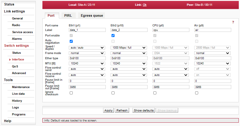
Configuration of port settings
- Port name
Identification of the internal switch port. The switch ports are connected to an external port or to an internal device (radio modem, management CPU).
Eth1 (port1) — The external port (with RJ45 interface) labeled “ETH1+POE”.
Eth2 (port10) — The external port (with SFP interface) labeled “ETH2”.
CPU (port0) — The internal port to management CPU.
Air (port9) — The internal port to radio modem, i.e. link to the peer unit.
- Label
Name of each port on the switch (up to 15 characters).
- Port enable
Enables functionality of individual port on the switch. Each port can be enabled or disabled.
Warning When the port is disabled, no communication is possible through this port.
- Auto negotiation
Enables Auto-Negotiation functionality of individual port. Negotiation is an Ethernet procedure by which two connected devices choose common transmission parameters, such as speed, duplex mode and flow control. In this process, the connected devices first share their capabilities regarding these parameters and then choose the highest performance transmission mode they both support.
The device supports three types of Auto-Negotiation:
10/100/1000BASE-T Copper Auto-Negotiation. (IEEE 802.3 Clauses 28 and 40)
1000BASE-X Fibre Auto-Negotiation (IEEE 802.3 Clause 37)
SGMII Auto-Negotiation (Cisco specification)
Auto-Negotiation provides a mechanism for transferring information from the local unit to the link partner to establish speed, duplex and Master/Slave preference during a link session.
Auto-Negotiation is initiated upon any of the following conditions:Power up reset
Hardware reset
Software reset
Restart Auto-Negotiation
Transition from power down to power up
The link goes down
The 10/100/1000BASE-T Auto-Negotiation is based on Clause 28 and 40 of the IEEE 802.3 specification. It is used to negotiate speed, duplex and flow control over CAT5 (or higher) UTP cable. Once Auto-Negotiation is initiated, the device determines whether or not the remote device has Auto-Negotiation capability. If so, the device and the remote device negotiate the speed and duplex with which to operate.
If the remote device does not have Auto-Negotiation capability, the device uses parallel detect function to determine the speed of the remote device for 100BASE-TX and 10BASE-T modes. If a link is established based on the parallel detect function, it is then required to establish the link at half-duplex mode only. Refer to IEEE 802.3 clauses 28 and 40 for a full description of Auto-Negotiation.
1000BASE-X Auto-Negotiation is defined in Clause 37 of the IEEE 802.3 specification. It is used to auto-negotiate duplex and flow control over fibre cable.
If one side of the link enables 1000BASE-X Auto-Negotiation and the link partner does not, the link cannot linkup. The device implements an Auto-Negotiation bypass mode.
SGMII Auto-Negotiation. SGMII is a de-facto standard designed by Cisco. SGMII uses 1000BASE-X coding to send data as well as Auto-Negotiation information. However, the contents of the SGMII Auto-Negotiation are different than the 1000BASE-X Auto-Negotiation.Warning If one device provides Auto-negotiation and the other works with a manual link parameters setting (i.e. without Auto-negotiation) the link operates in half-duplex mode. If the manual setting is set to full-duplex, the “Out collisions” may occur.
- Speed / duplex
Ethernet link speed and duplex mode can be selected. Both parameters can be either auto negotiated or set manually. When the Auto negotiation parameter is disabled, only manual setting of the speed and duplex is possible. In most cases it is better to enable the auto negotiation and use “auto / auto” speed and duplex settings.
There are two possibilities to force the link to operate in specific speed and duplex:
Auto negotiation enabled. Select the desired Speed / duplex. The auto negotiation process advertises only this specified link mode. The link partner is asked to use it.
Auto negotiation disabled. Select the desired Speed / duplex. The link is set to this specified link mode. The link partner has to be set manually to the same mode.
- Frame mode
Ethernet Frame mode control defines the expected Ingress and the generated Egress tagging frame format for this port as follows:
normal
Normal Network mode uses industry standard IEEE 802.ac Tagged or Untagged frames. Tagged frames use an Ether Type of 0x8100. Ports that are expected to be connected to standard Ethernet devices should use this modeDSA
Inactive options are not required.provider
Provider mode uses user definable Ether Types per port (see Ether type parameter) to define that a frame is Provider Tagged. Ports that are connected to standard Provider network devices, or devices that use Tagged frames with an Ether Type other than 0x8100 should use this mode.Frames, that ingress this port with an Ether Type that matches the port’s “Ether Type” parameter will be considered tagged, will have the tag’s VID and PRI bits assigned to the frame (i.e. they will be used for switching and mapping), and will have the Provider Tag removed from the frame. If subsequent Provider Tags are found following the 1st Provider Tag, they too will be removed from the frame with their VID and PRI bits being ignored. Modified frames will be padded if required.
Frames, that ingress this port with an Ether Type that does not match the “Ether Type” parameter will be considered untagged. The ingressing frames are modified so they are ready to egress out Customer ports (Normal Network Frame Mode ports) unmodified.
Frames that egress this port will always have a tag added (even if they were already tagged). The added tag will contain this port’s “Ether Type” as its Ether Type. The PRI bits will be the Frame Priority assigned to the frame during ingress. The VID bits will be the source port’s Default VID bits (if the source port was in Normal Network mode), or the VID assigned to the frame during ingress (if the source port was in Provider mode).
ether type DSA
Valid only for the “p5 CPU” port.
Ether Type DSA mode uses standard Marvell DSA Tagged frame information following a user definable Ether Type (see Ether type parameter). This mode allows the mixture of Normal Network frames with DSA Tagged frames and is useful on ports that connect to a CPU.
Frames that ingress this port with an Ether Type that matches the port’s “Ether Type” will be considered DSA Tagged and processed accordingly. The frame’s Ether Type and DSA pad bytes will be removed so the resulting frame will be ready to egress out Marvell DSA Tag Mode ports unmodified. Frames that ingress this port with a different Ether Type will be considered Normal Network Frames and processed accordingly.
Marvell DSA Tag control frames that egress this port will always get the port’s “Ether Type” inserted followed by two pad bytes of 0x00 before the DSA Tag. Marvell DSA Tag Forward frames that egress this port can egress just like the control frames (with the added Ether Type and pad) or they can egress as if the port was configured in Normal Network mode. This selection is controlled by the port’s Egress Mode bits above.
- Ether type
Ethernet frame type (often called EtherType) is used to indicate which protocol is encapsulated in the payload of an Ethernet Frame. This parameter is important when one protocol is encapsulated to another protocol.
Examples:
Ether type Standard Comment 0x8100 IEEE 802.1q Double-tagged, Q-in-Q or C-tag stacking on C-tag. C-tag in IEEE 802.1ad frames. 0x88a8 IEEE 802.1ad S-Tag 0x88e7 IEEE 802.1ah S-Tag (backbone S-Tag) 0x9100 — It is used very often. For example an old non-standard 802.1QinQ protocol uses this value. See http://en.wikipedia.org/wiki/EtherType for further details. - MTU [B]
Defines maximum transmission unit (MTU) frame size allowed to be received or transmitted from or to a given physical port. This implies that a Jumbo frame may be allowed to be received from a given input port but may or may not be allowed to be transmitted out of a port or ports.
The possible values are 1522, 2048 and 10240 Bytes.
Note The definition of frame size is counting the frame bytes from MAC_DA through Layer2 CRC of the frame.
- Flow control send/receive (previously TX/RX)
It is the mechanism for temporarily stopping the transmission of data on an Ethernet network, so that the receiving node is not overwhelmed with data from transmitting node. It works according IEEE 802.3x standard. If allowed, speed of data receive in to the switch (from the connected device) is regulated by the switch sending out flow control pause frames (according parameter ‘Pause limit out’) to the connected device. If allowed, speed of data transmission out from the switch (to the connected device) is regulated by processing received in flow control pause frames (according parameter ‘Pause limit in’) sent by the connected device.
Enabling flow control allows use of buffers of connected active network elements for leveling uneven flow of user data. For correct operation it is necessary to also enable Flow control on the connected device. Flow control is handled by sending Pause frames to the connected device. Possible values:
off — Flow control is disabled.
on — Flow control is enabled (forced to be active).
auto — Sending pause packets is advertised and depends on result on the auto-negotiation process. Auto-Negotiation has to be supported and enabled on the port to take effect.
Important For optimal utilization of Ethernet switch buffers and maximal operational speed of the link it is recommended to upgrade unit to the latest FW version and apply its defaults to ensure optimal buffers cooperation. Optimal performance may require playing a bit with Pause limit parameters to optimize the communication with the switch or router connected to the MW unit.
Note Additional link performance and better utilization of all available buffers in transmitting network could be typically achieved by configuring Flow Control between the MW unit and the nearest switches feeding the link by data. Important for incoming data are parameters ‘Flow Control send’ on ports ‘Eth1(p1)’ and/or ‘Eth2(p10)’, which needs to be set to values ‘auto’ or ‘on’ (the value to use depends on the switch).
FW versions 1.0.16.0 and earlier require RX Flow Control for port ‘Air (p9)’ on both units to be set to ‘on’. The only exception is FW version 1.0.14.0 with activated ‘Unit 24S compatibility’ (for more info see ‘Setting up a link between RAy3-24S and other hardware variant of RAy3-24’ in Chapter 8, Troubleshooting).
- Pause limit in [frame]
Value limits the number of continuous Pause refresh frames that can be received on this port (if full-duplex) or the number of 16 consecutive collisions (if half-duplex). Pause limit in [frame] When a port has flow control enabled, this parameter can be used to limit how long this port can be Paused or Back Pressured off to prevent a port stall through jamming.
The Flow Control on the port is (temporarily) disabled when the Pause refresh frames count exceeds the value of this parameter.
Setting this parameter to 0 will allow continuous jamming to be received on this port.
- Pause limit out [frame]
Value limits the number of continuous Pause refresh frames that can be transmitted from this port – assuming each Pause refresh is for the maximum pause time of 65536 slot times. When full-duplex Flow Control is enabled on this port, this parameter is used to limit the number of Pause refresh frames that can be generated from this port to keep this port’s link partner from sending any data.
Clearing this parameter to 0 will allow continuous Pause frame refreshes to egress this port as long as this port remains congested.
Setting this parameter to 1 will allow 1 Pause frame to egress from this port for each congestion situation.
Setting this parameter to 2 will allow up to 2 Pause frames to egress from this port for each congestion situation, etc.
- Ignore checksum
Enables ignoring Frame checksum (FCS) – or in other words – Force good FCS in the frame. When this parameter is not set (default behavior), frames entering this port must have a good CRC or else they are discarded. When this parameter is set, the last four bytes of frames received on this port are overwritten with a good CRC and the frames are accepted by the switch (assuming that the frame’s length is good and it has a destination).
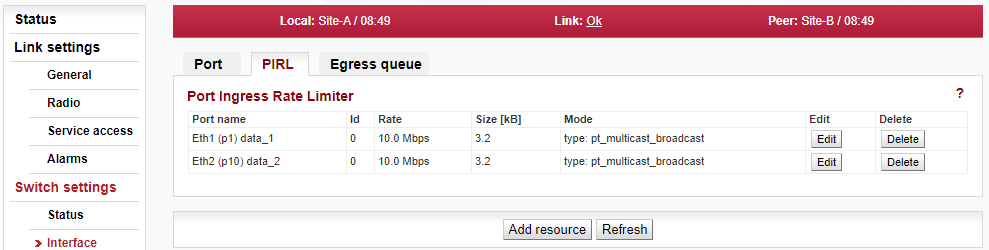
Page allows to configure PIRL – Port-based Ingress Rate Limiter.
It is a useful feature to limit bursts and storms of packets according different services, priorities and other network parameters to optimize the usage of limited capacity of wireless link.
The device supports per port TCP/IP ingress rate limiting along with independent Storm prevention. Port based ingress rate limiting accommodates information rates from 64 kb/s to 1 Mb/s in increments of 64 kb/s, from 1 Mb/s to 100 Mb/s in increments of 1 Mb/s and from 100 Mb/s to 1000 Mb/s in increments of 10 Mb/s.
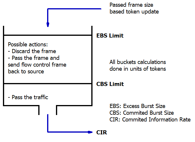
In addition to this, the device supports Priority based ingress rate limiting. Given ingress rate resource can be configured to track any of the four priority traffic types. The device supports a color- blind leaky bucket scheme, one of the popular schemes for implementing rate limiting. The way a leaky bucket scheme works is that the bucket drains tokens constantly at a rate called Committed Information Rate (CIR) and the bucket gets replenished with tokens whenever a frame is allowed to go through the bucket. All calculations for this bucket are done in tokens. Therefore, both bucket decrementing and incrementing is performed using tokens (i.e. frame bytes are converted into bucket tokens for calculation purposes).
The traffic below Committed Burst Size limit (CBS Limit) is passed without any further actions. If the traffic burst were to continue and the bucket token depth approaches closer to the Excess Burst Size limit (EBS Limit) by less than the CBS Limit, then a set of actions are specified. Note that if the frame gets discarded then the equivalent number of tokens for that frame will not get added to the bucket.
There are two default ingress limiting rules already configured in the switch default configuration. They limit the maximum allowed ARP traffic coming to the CPU port to 10 Mb/s from Eth1 and 10 Mb/s from Eth2 ports.
- Port name
Identification of the internal switch port. The switch ports are connected to an external port or to an internal device (radio modem, management CPU).
Eth1 (port1) — The external port (with RJ45 interface) labeled “ETH1+POE”.
Eth2 (port10) — The external port (with SFP interface) labeled “ETH2”.
CPU (port0) — The internal port to management CPU.
Air (port9) — The internal port to radio modem, i.e. link to the peer unit.
- ID
Unique ID of ingress rate resource. Each port can be assigned up to five different ingress rate resources.
Each resource defines a rule (filter) for the incoming frame. If the rule is met, the frame is affected (as set by the EBS limit action parameter). If the incoming frame doesn’t meet any rule, it is not affected by PIRL. The frame is accepted and forwarded further to the switch engine.
- Rate [Mb/s or fps]
The Bucket Rate. It is dependent on the Bucket Rate factor and the Bucket increment.
The calculation is estimated as the real data throughput depends on frame size. The Accounted bytes parameter affects this as well.
The formula for the rate (in bits or frames per second) is as follows:
rate = α * BRF / BI.
Where α is constant, which is 62 500 000 for Accounted bytes=”frame”, and is 500 000 000 for Accounted bytes=”layer1″. BRF is Bucket Rate factor and BI is Bucket increment.
- Size [kB]
The Burst allocation buffer size depends on the Bucket increment, the Committed Burst Size limit or the Excess Burst Size limit.
The formula for the BA is as follows:
BA = xBS / BI.
Where xBS can be either the Committed Burst Size limit CBS for the green bucket size or the Excess Burst Size limit EBS for the yellow bucket size and BI is the Bucket increment.
In order for the rate limiting to be accurate, it is required that bucket size is larger than max. frame size (MTU).
The Burst allocation size should be less than switch internal memory which is 250 kB.
- Mode
Rate type or Traffic type of rate limiting. See Bucket type parameter.
- Edit
The button opens for selected PIRL resource a new window, where all its parameters can be edited (for details see ‘PIRL resource configuration’).
- Delete
The button deletes selected PIRL resource.
- Add resource
The button creates a new PIRL resource and opens a new window, where all its parameters can be configured (for details see ‘PIRL resource configuration’).
PIRL resource configuration
This window opens after pushing button ‘Edit resource’ or ‘Add resource’ on page ‘PIRL’ (for details see above).
Each port can be assigned up to five different ingress rate resources.
Each resource defines a rule (filter) for the incoming frame. If the rule is met, the frame is affected (as set by the EBS limit action parameter). If the incoming frame doesn’t meet any rule, it is not affected by PIRL. The frame is accepted and forwarded further to the switch engine.
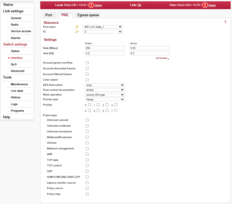
Resource
Unique identification of added/edited resource. The  icon indicates which parameter fields are taken as the unique
identifier in the database. Those 2 fields ensure each record is unique and must not be
duplicated.
icon indicates which parameter fields are taken as the unique
identifier in the database. Those 2 fields ensure each record is unique and must not be
duplicated.
- Port name, ID
Both parameters are described above (in section ‘PIRL Setup’).
Settings
All parameters of added/edited PIRL resource which can be configured.
- Rate, Size [Mb/s or fps]
Both parameters are described above (in section ‘PIRL Setup’).
- Advanced
(small active text on the right, just below line ‘Size’)Allows ‘Advanced configuration’ – more parameters appear.
- Accounted bytes
(appears only if ‘Advanced configuration’ is activated)This parameter determines which frame bytes are to be accounted for in the rate resource’s rate limiting calculations. There are four different supported configurations:
Frame — Frame based configures the rate limiting resource to account for the number of frames from a given port mapped to this rate resource.
layer 1 — Preamble (8bytes) + Frame’s DA to CRC + IFG (inter frame gap, 12 bytes)
layer 2 — Frame’s DA to CRC
layer 3 — Frame’s DA to CRC – 18 – 4 (if the frame is tagged)
A frame is considered tagged if it is either Customer of Provider tagged during ingress.
- Bucket increment
(appears only if ‘Advanced configuration’ is activated)Bucket increment (BI) indicates the amount of tokens that need to be added for each byte of the incoming frame.
- Rate factor
(appears only if ‘Advanced configuration’ is activated)This is a bucket factor (green or yellow) which determines the amount of tokens that need to be decremented for each rate resource decrement (which is done periodically based on the Committed Information Rate).
- Limit CBS/EBS
(appears only if ‘Advanced configuration’ is activated)Excess Burst Size limit – used for the yellow bucket. Committed Burst Size limit – used for the green bucket.
- Color mode
(appears only if ‘Advanced configuration’ is activated)Indication of the current color mode. Possible values: Single rate two color, Single rate three color, Dual rate three color.
- Account green overflow
false = Green and Yellow buckets are isolated when in Color Aware modetrue = Green and Yellow buckets are connected when in Color Aware mode
- Account discarded frames
This parameter decides whether the ingress rate limiting logic accounts for frames that have been discarded by the queue controller due to output port queue congestion reasons. To account for all frames coming into a given port associated with this rate resource, this parameter needs to be set.
- Account filtered frames
This parameter decides whether the ingress rate limiting logic accounts for frames that have been discarded because of ingress policy violations. To account for all frames coming into a given port associated with this rate resource, this parameter needs to be set.
- Color aware
false = color blind mode
true = color aware mode
- EBS limit action
This parameter controls what kind of action is performed when the EBS limit has been exceeded. Two types of action can be selected:
drop — The frame that was received on the port will get discarded.
flow control — The frame that was received on the port will get discarded.
In this mode an Ethernet flow control frame gets generated (if the flow control is enabled for that port) and sent to the source port but the incoming frame gets passed through the rate resource. If the port is operating in half-duplex mode then the port gets jammed.
Flow control mode is expected to be programmed on ports that have a trusted flow control mechanism available. The EBS limit action is a per-port characteristic. If a port has multiple rate resource buckets then all buckets enabled are expected to be programmed with the same EBS limit action.- Flow control de-assertion
This parameter controls the flow control de-assertion when EBS limit action is set to generate a flow control message. There are two modes available:
empty — Flow control gets de-asserted only when the ingress rate resource has become empty.
CBS limit — Flow control gets de-asserted when the ingress rate resource has enough room to accept at least one frame of size specified by the CBS limit.
For example, if the CBS limit is programmed to be 2k Bytes, then the flow control will get de-asserted if there is at least 2k Bytes worth of tokens available in the ingress rate resource.
- Mask operation
This parameter controls whether an ingress frame must meet both Priority and Frame type requirements to be counted for ingress rate calculations or if meeting only one requirement is sufficient to be counted for ingress rate calculations for this rate resource.
- Priority type
frame – use FPri assigned to the frame
queue – use QPri assigned to the frame
- Priority
Any combinations of the eight queue priorities can be selected. Frames with marked priority are accounted for in this ingress rate resource.
If there is no priority selected, priority of the frame does not have any affect on the ingress rate limiting calculations done for this ingress rate resource.
- Frame type
Any of the following frame types can be selected to be tracked as part of the rate resource calculations:
Unknown unicasts, Unknown multicasts, Unknown broadcast, Multicasts/Broadcasts, Unicasts, Network management, ARP (Address Resolution Protocol), TCP data, TCP control, UDP, group IGMP, ICMP, GRE, IGRP and L2TP covers Non-TCPUDP, Ingress monitor source, Policy mirror, Policy trap.
More than one frame type can be selected for a given rate resource.
The Egress queue page allows to set parameters for eight output (egress) queues available in internal Ethernet switch of the unit.
Each queue is used to store frames with given priority (as set in 802.1p and DSCP configuration). The queue depth is controlled dynamically to reach maximum utilization of the switch memory. The queue frame egress is controlled by scheduling algorithms as described further below.
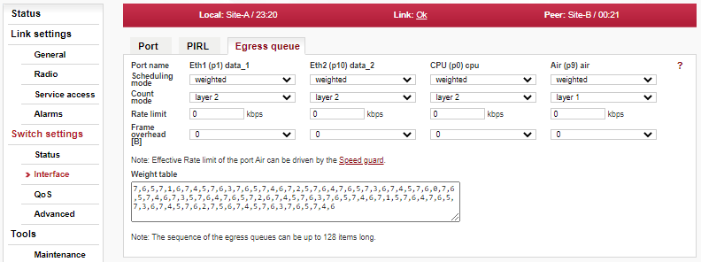
- Port name
Identification of the internal switch port. The switch ports are connected to an external port or to an internal device (radio modem, management CPU).
Eth1 (port1) — The external port (with RJ45 interface) labeled “ETH1+POE”.
Eth2 (port10) — The external port (with SFP interface) labeled “ETH2”.
CPU (port0) — The internal port to management CPU.
Air (port9) — The internal port to radio modem, i.e. link to the peer unit.
- Scheduling mode
The device supports strict priority, weighted round robin, or a mixture on a per egress port selection basis.
In the strict priority scheme all top priority frames egress for a port until that priority’s queue is empty, then the next lower priority queue’s frames egress, etc. This approach can cause the lower priorities to be starved out preventing them from transmitting any frames but also ensures that all high priority frames egress the switch as soon as possible.
In the weighted scheme an 33, 25, 17, 12, 6, 3, 2, 1 weighting is applied to the eight priorities unless an alternate weighting is programmed into the QoS Weights Table. This approach prevents the lower priority frames from being starved out with only a slight delay to the higher priority frames.
Some applications may require the top priority queue, or the top ‘n’ priority queues to be in a fixed priority mode while the lower queues work in the weighted approach. All scheduling modes are selectable on a per port basis.
The port scheduling mode can be one of the following values:
- weighted
Use weighted round robin for all queues.
- weighted 0 – 6
Use strict priority for queue 7 and weighted round robin for queues 6 to 0
- weighted 0 – 5
Use strict priority for queues 7 and 6, and weighted round robin for queues 5 to 0
- weighted 0 – 4
Use strict priority for queues 7 to 5, and weighted round robin for queues 4 to 0
- weighted 0 – 3
Use strict priority for queues 7 to 4, and weighted round robin for queues 3 to 0
- weighted 0 – 2
Use strict priority for queues 7 to 3, and weighted round robin for queues 2 to 0
- weighted 0 – 1
Use strict priority for queues 7 to 2, and weighted round robin for queues 1 to 0
- strict
Use strict priority for all queues.
- Count mode
Egress rate limiting count mode. This parameter is used to control which bytes in the transmitted frames are counted for egress rate limiting as follows:
frame — The egress rate limiting is done based on frame count [fps] as opposed to the byte count [kb/s] of the packet.
layer 1 — Preamble (8bytes) + Frame’s DA to CRC + IFG (inter frame gap, 12 bytes)
layer 2 — Frame’s DA to CRC
layer 3 — Frame’s DA to CRC – 18 – 4 (if the frame is tagged)
Only one tag is counted even if the frame contains more than one tag. A frame is considered tagged if the egress frame going out onto the wire is tagged.
- Rate limit
Egress data rate shaping. When Rate = 0 egress rate limiting is disabled.
Note The Count mode parameter is used to control which bytes in the transmitted frames are counted for egress rate limiting.
If the egress shaping is controlled by frame rate, the desired frame rate can vary from 7.6k to 1.488M frames per second. Valid values are between 7632 and 1488000.
If the egress shaping is controlled by bit rate, the desired rate can vary from 64 kb/s to 1 Gb/s in the following increments:
Desired rate between 64 kb/s and 1 Mb/s in increments of 64 kb/s
Desired rate between 1 Mb/s to 100 Mb/s in increments of 1 Mb/s
Desired rate between 100 Mb/s to 1 Gb/s in increments of 10 Mb/s
Desired rate between 1 Gb/s to 10 Gb/s in increments of 100 Mb/s
Therefore, the valid values are:
64, 128, 192, 256, 320, 384,…, 960,
1000, 2000, 3000, 4000, …, 100000,
110000, 120000, 130000, …, 1000000,
1100000, 1200000, 1300000, …, 10000000.
Note The activated “Speed guard” function overwrites the current Rate limit setting.
- Frame overhead [B]
This parameter is used to adjust the number of bytes that need to be added to a frame’s IFG (inter frame gap) on a per frame basis. This is to compensate for a protocol mismatch between the sending and the receiving stations. For example, if the receiving station were to add more encapsulations to the frame for the nodes further downstream, this per frame adjustment would help reduce the congestion in the receiving station.
This adjustment, if enabled, is added to the Egress Rate Control’s calculated transmitted byte count meaning Egress Rate Control must be enabled for this Frame Overhead adjustment to work.
- Weight table
The weighted round robin alternate weighting can be defined here. The sequence of the output queue numbers (0,1,2 to 7) defines the sequence of the output queue frame egressing. This sequence can be up to 128 items long.
Quality of Service (QoS) is the ability to provide different priorities to different applications, users, or data flows, or to guarantee a certain level of performance to a data flow. QoS using 802.1p and DSCP are implemented.
The ingress block has the task of determining the priority of each frame to be used for the internal Queue Controller (QPri) as well as the priority assigned to the frame (FPri) if the frame egresses the switch tagged. The classification as to if the frame is discard eligible (Yellow) is also determined. The Ingress block does not perform the QoS switching policy, which is the task of the Queue Controller. Instead, it has the job of determining the QPri and FPri assigned to each frame for the Queue Controller and Egress block.
Port based QoS parameters makes it possible to control QoS based on the ingress port.
Every frame entering the switch gets two priority values assigned to it. One priority value is used inside the switch only to determine which output queue the frame is to be mapped into. This is called QPri for queue priority. The other priority value is used outside the switch only to mark the frame’s IEEE PCP bits if the frame egresses a port tagged. This is called FPri for frame priority. A third parameter, called Yellow, is also assigned to the frame. If Yellow=1 the frame is considered eligible for discard if congestion warrants it.
The initial QPri, FPri and Yellow values are assigned differently to various frame types. Some frames are assigned more than one set of QPri, FPri and Yellow values. For example, an IEEE tagged IPv4 frame will get a set of values from the IEEE tag, another set from the IPv4 header and another set from the port. Some applications require that the port’s default priority be used regardless of the contents of the frame. The Initial priority parameter selects this default priority.
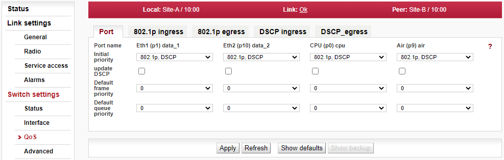
- Update DSCP
If the parameter is enabled, the DSCP field in frames that egress this port is updated.
- Default frame priority
All ingressing frames are assigned a default FPri (frame priority) and QPri (queue priority). The default value for Yellow is zero (i.e. the frame is not discarded eligible).
- Default queue priority
All ingressing frames are assigned a default FPri (frame priority) and QPri (queue priority).
The IEEE 802.1p QoS technique also known as class of service (CoS), is using a 3-bit field called the Priority Code Point (PCP) within an Ethernet frame header when using VLAN tagged frames as defined by IEEE 802.1Q. It specifies a priority value of between 0 and 7 inclusive that can be used by QoS disciplines to differentiate traffic. The value 0 is generally taken as the lowest priority and 7 as the highest priority.
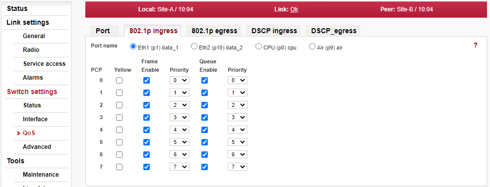
- Priority code point (PCP)
Priority Code Point (PCP) value to which the following parameters (Yellow, Frame Enable, Frame Priority, Queue Enable and Queue Priority) belong to.
- 802.1p yellow
When this parameter is enabled any IEEE tagged frame (having given PCP priority) that accesses this port will be given an initial IEEE color of Yellow. This color will be assigned to the frame using the same rules used to select the frame’s initial FPri and QPri values.
- Enable 802.1p frame priority
When the Frame Enable parameter is checked, the Frame Priority (FPri) mapping is enabled.
- 802.1p frame priority
The Frame Priority value is taken as the frame’s initial IEEE FPri in case the Frame Enable is checked.
- Enable 802.1p queue priority
When the Queue Enable parameter is checked, the Queue Priority (QPri) mapping is enabled.
- 802.1p queue priority
The Queue Priority value is taken as the frame’s initial IEEE QPri in case the Queue Enable is checked.
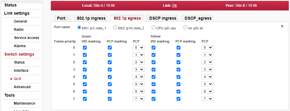
- Frame priority for 802.1p mapping
Frame priority value to which the following Green and Yellow parameters (VID marking, PCP marking and PCP) belong to.
- VID marking
Enable/disable VID marking for the given Frame priority. When the parameter is disabled frames assigned with this FPri in ingress will not get their VID field updated even if the frame egresses Tagged (normally all egressing Tagged frames get their VID updated to the value assigned in ingress).
- PCP marking
Enable/disable PCP marking for the given Frame priority. When the parameter is disabled frames assigned with this FPri in ingress will not get their PCP & CFI fields updated even if the frame egresses Tagged (normally all egressing Tagged frames get their FPri & CFI bits updated to the value assigned in ingress).
- 802.1p frame PCP
Frame Priority Code Point. This parameter contains the new PCP or FPri value that is assigned to frames that egress this port. The FPri assigned to the frame in ingress is used to access this table.
The DSCP stands for Differentiated services Code Point which is a 6-bit value stored within the IP header. The QoS techniques using those bits are called DiffServ or Differentiated services.
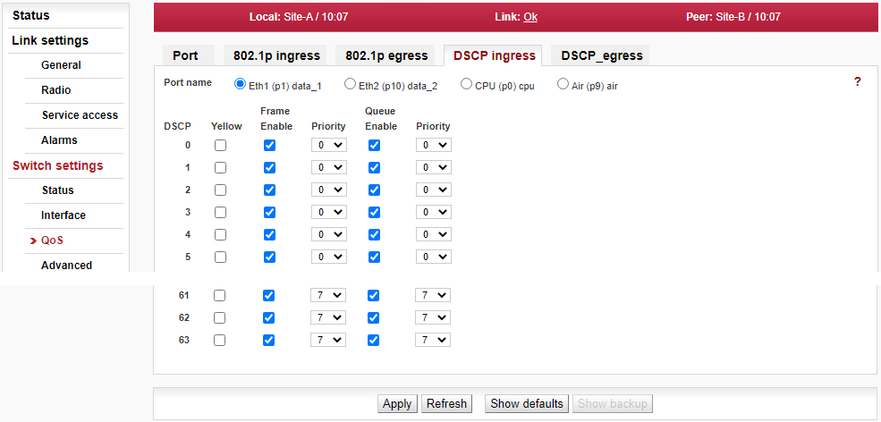
- DSCP
DSCP value to which the following parameters (Yellow, Frame Enable, Frame Priority, Queue Enable and Queue Priority) belong to.
- DSCP Yellow
When this parameter is enabled any IP frame that accesses this entry will be given an initial IP color of Yellow. This color will be assigned to the frame using the same rules to select the frame’s initial FPri and QPri values.
- Enable DSCP frame priority
When this parameter is enabled, the Frame Priority Mapping will be used.
- DSCP frame priority
The value set in this parameter is used as the frame’s initial IP Frame priority as long as Enable is checked.
- Enable DSCP queue priority
When this parameter is enabled, the queue Priority mapping will be used.
- DSCP queue priority
The value set in this parameter is used as the frame’s initial IP Queue priority as long as Enable is checked.
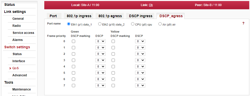
- Port name
Selects the port on Eth switch for which settings below are shown/updated.
- Frame priority
Frame priority value for DSCP mapping to which the following Green and Yellow parameters (DSCP marking and DSCP) belong to.
- DSCP marking
When this parameter is enabled for some Frame priority, the Frame Priority Mapping will be used, i.e. IP frames assigned with this FPRi in ingress will get their DSCP fields updated.
- DSCP
This parameter defines the new DSCP value that is assigned to frames that egress this port. The FPri assigned to the frame in ingress is used to access this table.
The VLAN (Virtual LAN) page allows to set VLAN related and global parameters needed for VLAN functionality of the unit.
| Important | |
|---|---|
Parameters in VLAN page are tightly related to the settings configured in pages STU and VTU. For a proper functionality all parameters inside pages VLAN, STU and VTU have to correspond to each other. |
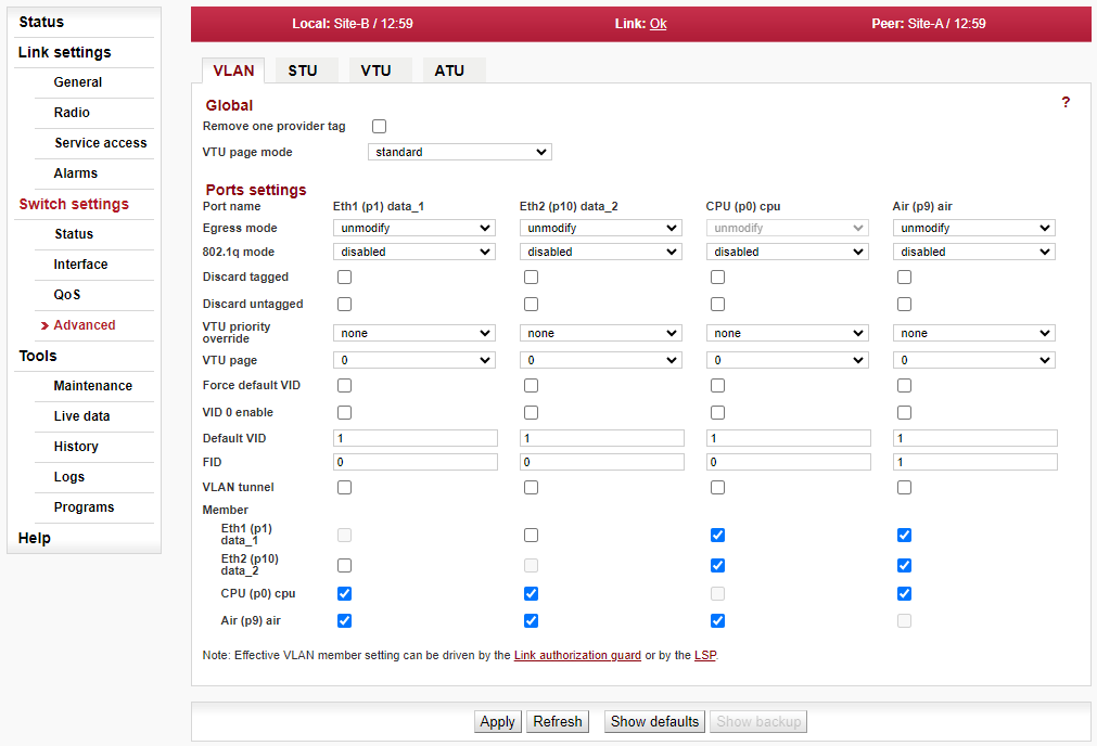
Global
- Remove one provider tag
When this parameter is enabled and a port is configured as a Provider Port, recursive Provider Tag stripping will NOT be performed. Only the first Provider Tag found on the frame will be extracted and removed. Its extracted data will be used for switching.
When this parameter is disabled and a port is configured as a Provider Port, recursive Provider Tag stripping will be performed. The first Provider Tag’s data will be extracted and used for switching, and then all subsequent Provider Tags found in the frame will also be removed. This will only occur if the port’s “Ether type” is not 0x8100 (recursive Provider Tag removal cannot be performed when the Provider’s Ether Type is equal to 0x8100).
- VTU page mode
The VTU page mode supports alternate VID look up results based on if a frame is a Multicast (including Broadcasts) or not, or based on what source port the frame came in on, or if the frame was properly Provider tagged or not.
Ports settings
- Port name
Identification of the internal switch port. The switch ports are connected to an external port or to an internal device (radio modem, management CPU).
Eth1 (port1) — The external port (with RJ45 interface) labeled “ETH1+POE”.
Eth2 (port10) — The external port (with SFP interface) labeled “ETH2”.
CPU (port0) — The internal port to management CPU.
Air (port9) — The internal port to radio modem, i.e. link to the peer unit.
- Egress mode
This parameter determines the makeup of frames when they egress this port. The Egress mode behavior is affected by the Frame mode (menu Interface/Port advanced/Frame mode) parameter.
Frame mode … normal:
unmodify — Frames are transmitted unmodified.
untag — Remove the tag from any tagged frame.
tag — Add a tag (e.g. according to “Default VID”) to any untagged frame. Ethernet frame type is set to 0x8100.
Frame mode … provider:unmodify — Use this mode when “Frame mode” is set to “provider”.
untag — not used
tag — not used
Frame mode … ether type DSA:unmodify — not used
untag — not used
tag — not used
ether type tag — Add a tag (e.g. according to “Default VID”) to any untagged frame. Ethernet frame type is set according to “Ether type” parameter (menu Switch settings/Interface/Port advanced).
- 802.1q mode
This parameter determines if 802.1q base VLANs are used along with port based VLANs for this Ingress port. It also determines the action to be taken if an 802.1q VLAN Violation is detected. VLAN barriers (both port based and 802.1q based) can be bypassed by VLAN Tunnel.
disabled — Use Port Based VLANs only. The VID assigned to the frame is the port’s Default VID which is used as the VID in the Provider Tag if the frame egresses a Provider port.
fallback — Enable 802.1q for this Ingress port. Do not discard Ingress Membership violations and use the VLAN Table bits if the frames’ VID is not contained in the VTU.
The ingressing frames are not discarded and it doesn’t matter if the frames’ VID is a member of the VTU.
check — Enable 802.1q for this Ingress port. Do not discard Ingress Membership violation but discard the frame if its VID is not contained in the VTU.
The ingressing frames’ VID must be configured in the VTU to enable it to ingress. The VTU “Member tag” parameter doesn’t have any effect.
secure — Enable 802.1q for this Ingress port. Discard Ingress Membership violations and discard frames whose VID is not contained in the VTU.
The ingressing frame is checked fully against the record in the VTU table. The “VID” and the “Member tag” parameters are validated to allow the frame to ingress.
- Discard tagged
When this parameter is enabled all non-MGMT frames that are processed as tagged are discarded as they enter this switch port. Priority only tagged frames (with a VID of 0x000) are considered untagged. This feature works whether 802.1q is enabled on the port or not.
If the port is configured in Provide Mode and this parameter is enabled, frames that contain an Ether Type that matches the port’s PortEType (“Ether type” parameter) that have a non-zero VID will be discarded.
- Discard untagged
When this parameter is enabled all non-MGMT frames that are processed as untagged are discarded as they enter this switch port. Priority only tagged frames (with a VID of 0x000) are considered untagged. This feature works if 802.1q is enabled on the port or not.
If the port is configured in Provide Mode and this parameter is enabled, frames that don’t contain an Ether Type that matches the port’s PortEType (“Ether type” parameter) that have a non-zero VID will be discarded.
- VTU priority override
When this parameter is set to anything other than “none”, VTU priority overrides can occur on this port. A VTU priority override occurs when the determined VID of a frame results in a VID whose “Use VID priority” parameter is enabled. When this occurs three (other than “none”) forms of priority overrides are possible:
none — Normal frame priority processing occurs.
frame — The “VID priority” value assigned to the frame’s VID (in the VLAN database) is used to overwrite the frame’s previously determined FPri (frame priority). If the frame egresses tagged the priority in the frame will be this new “VID priority” value – the frame is permanently modified.
queue — The “VID priority” value assigned to the frame’s VID (in the VLAN database) is used to overwrite the frame’s previously determined QPri (queue priority). The QPri is used internally to map the frame to one of the egress queues inside the switch. QPri override will not affect the contents of the frame in any way.
frame + queue — Both the above overrides take place on the frame.
The VTU Priority override has higher priority than the port’s Default Priority and the frame’s IEEE and/or IP priorities. The priority determined by the frames’ VID can however be overridden by the frames’ SA and/or DA Priority Overrides.
- VTU page
When “VTU page mode” is set to value “port” this setting is used to determine which VTU page is used for frames ingressing this port. This supports different VTU lookup results for the same VID based on the value of this bit and allows Core ports to use one set of VTU values while Edge ports use a different set.
- Force default VID
Force to use Default VID. When 802.1q is enabled on this port and this parameter is enabled, all Ingress frame’s VID are ignored and the “Default VID” is assigned and replaced into the frame (if the frame egresses tagged). When this parameter is disabled all IEEE802.3ac Tagged frames with a non-zero VID use the frame’s VID unmodified. When 802.1q is disabled on this port, this bit has no effect.
- VID 0 enable
When this bit is cleared to a zero normal network switching occurs (i.e., a frame received with a VID of 0x000 will get an initial VID assignment from the Port’s Default VID from Port offset 0x07). When this bit is set to a one frames received with a VID of 0x000 will NOT get an initial VID assignment from the port’s Default VID – it will get an initial VID assignment value of 0x000 instead.
- Default VID
Default VLAN Identifier. When 802.1q is enabled on this port the Default VID parameter is used as the IEEE Tagged VID added to untagged or priority tagged frames during egress that ingressed from this port. It is also used as a tagged frame’s VID if the frame’s VID was 0x000 (i.e., it is a priority tagged frame) or if the port’s “Force Default VID” is enabled.
When 802.1q is disabled on this port, the Default VID field is assigned to all frames entering the port (whether tagged or untagged). This assignment is used internal to the switch.
- FID
Port’s Default Filtering Information Database (FID). This parameter can be used with non-overlapping VLANs to keep each VLAN’s MAC address mapping database separate from the other VLANs. This allows the same MAC address to appear multiple times in the address database (at most one-time per VLAN) with a different port mapping per entry. This field is overridden by the FID returned from a VTU hit and it should be zero if not used. It must be a unique number for each independent, non-overlapping, address database if used.
- VLAN tunnel
When this parameter is disabled, the port based VLANs defined in the VLAN Table, 802.1q VLANs defined in the VTU and Trunk Masking are enforced for ALL frames.
When this parameter is enabled, the port based VLAN Table masking, 802.1q VLAN membership masking and the Trunk Masking are bypassed for any frame entering this port with a DA that is currently ‘static’ in the ATU. This applies to unicast as well as multicast frames.
While enabled, the Unicast frames with the management CPU DA can go from the Eth1 and Eth2 ports in to the CPU port. The static record with the CPU DA in the ATU table has to be configured (it is pre-configured by default).
- Member (VLAN Table)
The In Chip Port based VLAN Table contains parameters used to restrict the output ports to which an input port can send frames. These parameters (VLAN Table bits) are used for all frames, except for MGMT frames, even if 802.1q is enabled on this port. These parameters restrict where a port can send frames to (unless a VLANTunnel frame is being received). If ForceMap (Learning) is enabled, these parameters indicate which port or ports all frames that ingress this port are sent to overriding the mapping from the address database. The default setting prevents sending frames from Eth1 to Eth2 and vice versa. This is very important for separating different networks (e.g. different customers) connected to separate user ports.
| Note | |
|---|---|
The parameter Link authorization guard (from menu Link Settings > Service access > Services) affects the user data flow through the Air channel. When the Link authorization guard is enabled, the user Ethernet ports to Air port connection control is disabled. Parameter status of user Ethernet to Air port connection changes dynamically according to Link authorization status. |
The STU (Spanning Tree Unit) is related to VLAN functionality (pages STU, VTU and VLAN has to correspond to each other). The per VLAN STU in the device supports user commands to access and modify the contents of the Port State database.
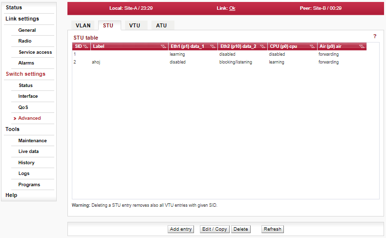
- SID
VTU 802.1s (MSTP) Port State Information Database number. This parameter indicates the SID number that is associated with the 802.1s “Port state” parameter. It is essential to define the SID to be able to create records in the VTU (VLAN Table).
- Label
A custom string label for a STU entry.
- Port state (for ports Eth1, Eth2, CPU and Air)
This parameter is used to support 802.1s per VLAN spanning tree. Port states are valid for frames with a VID that is associated to this SID:
disabled — Use non-VLAN Port States (i.e., the port’s default Port State) for this port.
blocking/listening
learning
forwarding
This “Eth port state” takes precedence over the port’s Port State bits unless the port’s Port State (driven by STP) is Disabled (which prevents all frames from flowing).
- Add entry
Creates a new STU database entry. New window is opened to allow to enter values to each field (see their meanings above). The ‘Primary key icon’
indicates which parameter field is taken as the unique
identifier in the database. This field entry ensures each record is unique and must
not be duplicated.
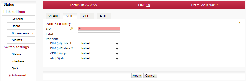
- Edit/Copy
Opens the configuration dialog for the selected STU database record. New window is opened to allow to modify values of each field (for layout and values see the explanation for ‘Add entry’ button).
Note Should the Primary key value be modified, the “other” record – identified by the entered Primary key – is added (if it does not exist yet) or modified (if it exists already).
- Delete
Deletes the selected STU database record.
The VTU (VLAN Table Unit) is related to VLAN functionality (pages STU, VTU and VLAN has to correspond to each other). Its records form the VLAN Table.
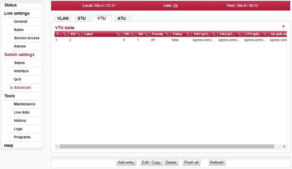
- Page
To be implemented yet.
- VID
VLAN ID. This parameter indicates the VID number that is associated with the Member tag, VTU Priority, VTU policy and the FID (Forwarding Information Database number).
- Label
A custom string label for a VTU entry.
- FID
Forwarding Information Database number. If separate address databases are used, this parameter indicates the address database number to use for all frames assigned with this VID. All MAC DA look-ups and SA learning will refer to the address database number defined by the FID associated with the frame’s VID. Multiple VID’s can use the same FID. If separate address databases are not used, the FID must be zero. The ATU database records are joined with the VTU database records via this number.
- SID
802.1s Information Database Number. If 802.1s per VLAN spanning tree is being used, this parameter indicate the spanning tree instance number to use for all frames assigned with this VID. Multiple VID’s can use the same SID. The STU database records are joined with the VTU database records via this number.
- Priority
Indicates status of parameters ‘VID Frame Priority’ and ‘VID Queue Priority’ (see their explanation below).
- VID frame priority
(appears only in windows ‘Add/Edit/Copy VTU entry’)VID Frame Priority Use. This parameter is used to indicate that frames assigned with this VID can have their priority overridden with the “VID priority” value (see below) if the port’s “VTU priority override” parameters is enabled to do so. See “VTU priority override” for more details. VID Priority override value when enabled by the “Use VID priority” parameter (see above). Used for priority override on ingressing frames. Enabling a priority on a VID will override the frame’s priority only if the port’s “VTU priority override” parameter is enabled to do so.
- VID queue priority
(appears only in windows ‘Add/Edit/Copy VTU entry’)VID Queue Priority Use. This parameter is used to indicate that frames assigned with this VID can have their priority overridden with the “VID priority” value (see below) if the port’s “VTU priority override” parameters is enabled to do so. See “VTU priority override” for more details. VID Priority override value when enabled by the “Use VID priority” parameter (see above). Used for priority override on ingressing frames. Enabling a priority on a VID will override the frame’s priority only if the port’s “VTU priority override” parameter is enabled to do so.
- Policy or VID policy
(‘VID policy’ appears in windows ‘Add/Edit/Copy VTU entry’)This parameter is used to indicate that frames assigned with this VID can have Layer 2 Policy actions applied to it if the port’s “Policy VTU” (menu Advanced/Monitoring, Policy/Policy) is enabled to do so.
- Don’t learn
(appears only in windows ‘Add/Edit/Copy VTU entry’)To be implemented yet.
- Filter UC/BC/MC
(appears only in windows ‘Add/Edit/Copy VTU entry’)To be implemented yet
- Member tag
(For ports Eth1, Eth2, CPU and Air). This parameter is used to indicate which ports are members of the VLAN (i.e., with the given VID) and if these VLANs frames should be tagged or untagged, or unmodified when exiting the port as follows:
egress unmodified — Port is a member of this VLAN and frames are to egress unmodified.
egress untagged — Port is a member of this VLAN and frames are to egress Untagged.
egress tagged — Port is a member of this VLAN and frames are to egress Tagged.
not member — Port is not a member of this VLAN. The result is that frames assigned with this VID cannot egress this port.
This parameter takes effect only if the “802.1q mode” parameter (see menu Advanced/VLAN) is set to “secure” mode.- Add entry
Creates a new VTU database entry. New window is opened to allow to enter values to each field (see their meanings above). The ‘Primary key icon’
indicates which parameter field is taken as the unique
identifier in the database. This field entry ensures each record is unique and must
not be duplicated.
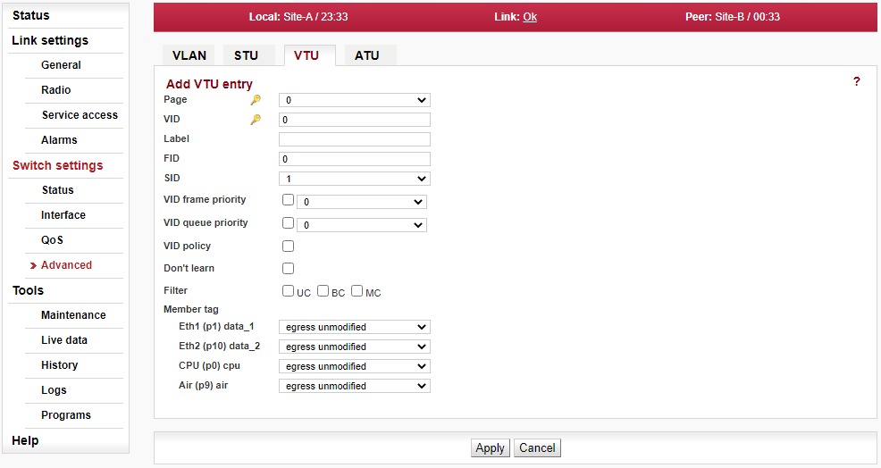
- Edit/Copy
Opens the configuration dialog for the selected VTU database record. New window is opened to allow to modify values of each field (for layout and values see the explanation for ‘Add entry’ button).
Note Should the Primary key value be modified, the “other” record – identified by the entered Primary key – is added (if it does not exist yet) or modified (if it exists already).
- Delete
Deletes the selected VTU database record.
- Flush all
Deletes the whole VTU database.
The Address Translation Unit (ATU) in the device supports user commands to access the contents of the MAC address database.
There is one static record which cannot be deleted. This is the management CPU record. The unicast frames directed to management are allowed to access the CPU port. The “VLAN tunnel” parameter is also used to enable the AP frames to access the CPU port.
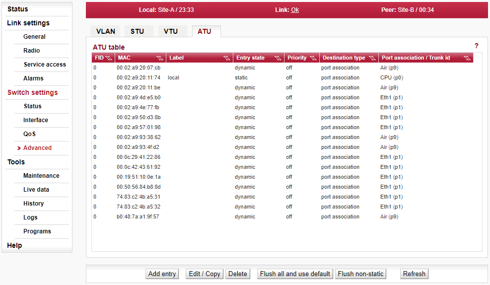
- FID
Forwarding Information Database number. If multiple address databases are not being used, this parameter must remain zero. If multiple address databases are being used, this parameter is used to set the desired address database number that is to be associated with this ATU Entry’s MAC Address. When frames ingress the switch, the VID assigned to the frame is used to access the VTU. The VTU returns the FID associated with that VID for MAC address lookups in to the ATU.
- MAC
MAC address associated with this ATU entry in the database number defined by the FID.
- Label
A custom string label for a ATU entry.
- Entry state
The Entry state parameter is used to determine the entry’s age or its type as follows:
static — Use for ordinary static entry.
static policy — Use for “Policy DA” and/or “Policy SA” (menu Advanced/Monitoring/Policy).
static non rate limiting — Use for “SA non rate limit” and/or “DA non rate limit” (menu Interface/PIRL).
static management — This value is used for the mapping of the DA even if the “DA mapping” parameter is disabled (menu Advanced/ATU settings).
dynamic — ordinary dynamic entry.
- Priority
Shows the actual MAC priority settings (for explanation see items ‘Use MAC priority’, ‘MAC frame priority’ and ‘MAC queue priority’ below).
- Use MAC priority
(appears only in windows ‘Add/Edit/Copy ATU entry’)Use this parameter to enable the “MAC priority” (see “MAC priority” description).
- MAC frame priority
(appears only in windows ‘Add/Edit/Copy ATU entry’)The MAC’s Frame Priority override value when enabled by the “Use MAC priority” parameter. Used for priority override on ingressing frames. Enabling a priority on a MGMT MAC address will override all priorities for these MGMT frames. Enabling a priority on a static, non-MGMT MAC address, will only override the frame’s priority if the port’s “DA priority override” or “SA priority override” parameters are enabled.
- MAC queue priority
(spears only in windows ‘Add/Edit/Copy ATU entry’)The MAC’s Queue Priority override value when enabled by the “Use MAC priority” parameter. Used for priority override on ingressing frames. Enabling a priority on a MGMT MAC address will override all priorities for these MGMT frames. Enabling a priority on a static, non-MGMT MAC address, will only override the frame’s priority if the port’s “DA priority override” or “SA priority override” parameters are enabled.
- Destination type
Shows the actual settings of port association, trunks, etc.
- Trunk member
(spears only in windows ‘Add/Edit/Copy ATU entry’)When this parameter is enabled, the MAC address is a member of a trunk – according to the “Trunk ID” parameter. When this parameter is disabled, the MAC address is associated with port(s) – according to the “Port association” parameter.
- Trunk ID
The Trunk ID associated with this MAC address. The port or ports that this DA MAC address is associated with is determined by the “Port association” parameter below. Use this parameter to ensure the proper unit management CPU is accessed when two units are connected in trunk.
- Port association
(For ports ETH1, ETH2, CPU and Air). Mask of ports associated with this MAC address.
- Add entry
Creates a new ATU database entry. New window is opened to allow to enter values to each field (see their meanings above). The ‘Primary key icon’
indicates which parameter field is taken as the unique
identifier in the database. This field entry ensures each record is unique and must
not be duplicated.
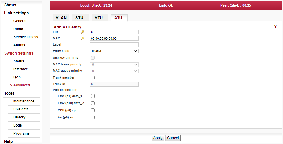
- Edit/Copy
Opens the configuration dialog for the selected VTU database record. New window is opened to allow to modify values of each field (for layout and values see Fig. 5.38, “Menu Switch settings > Advanced > ATU > Add Entry (or Edit Entry or Copy Entry)” above and for the description the explanation for Add entry button).
Note Should the Primary key value be modified, the “other” record – identified by the entered Primary key – is added (if it does not exist yet) or modified (if it exists already).
- Delete
Deletes the selected ATU database record.
- Flush all and use default
Deletes the whole ATU database and create default record(s).
- Flush non-static
Delete all but static ATU database records.
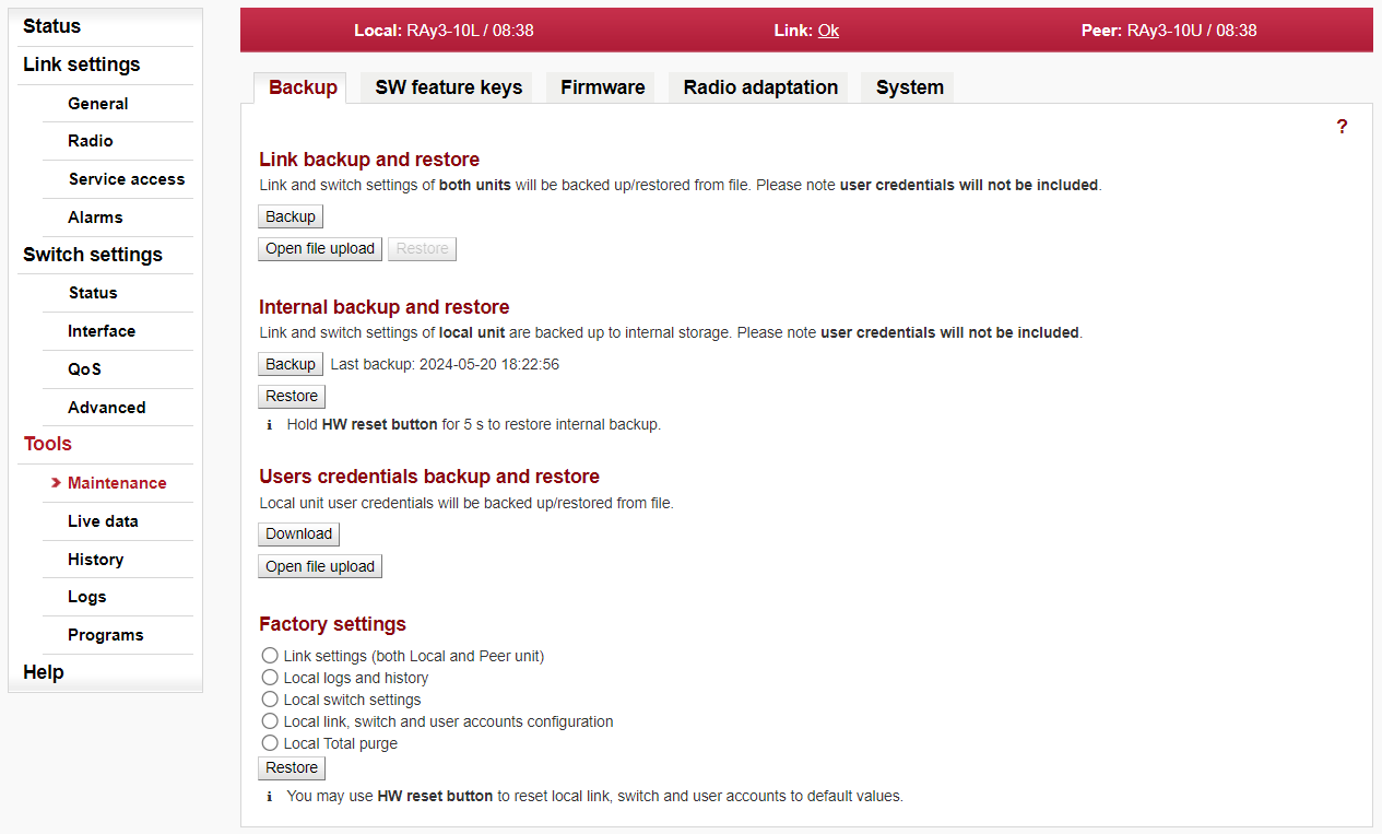
Link backup and restore
Link and switch settings of both units are backed up/restored to/from file. User accounts and SW keys are not backuped/restored by those functions.
Scope
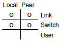
- Backup
Configuration is saved to backup file which is downloaded to management PC. The backup file name contains the date, time and unit serial number as follows:
yyyyMMddhhmm_SN_cnf_backup.tgz.- Open file upload
Upload configuration from a backup file into buffer. The current unit configuration is not affected. The uploaded configuration can be displayed using ‘Show backup’ button on particular configuration screens. The configuration of the entire unit can be restored (from this buffer) using ‘Restore’ button below.
- Restore
After the configuration backup file has been loaded into the unit buffer (using Open file upload button above), the whole unit configuration can be restored using ‘Restore’ button.
Internal backup and restore
It is possible to make a temporary backup of the local unit configuration. The backup is stored directly in the unit FLASH memory. User accounts and SW keys are not backuped/restored by those functions.
| Note | |
|---|---|
Such fast backup is strongly recommended before any manipulation of unit parameters or before antenna alignment, because it allows fast restore to the surely working configuration. This backup is totally independent from the backup to external file and its values are not dispayed using ‘Show backup’ button. |
Scope
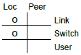
- Backup
Make a temporary backup of the unit configuration locally in to the unit FLASH memory.
- Restore
Restore (from the unit FLASH memory) the temporary backup of the unit configuration.
- Internal restore – HW button
The local temporary backup of the unit configuration can be also restored using the hardware button. The HW button is located next to the USB connector within the slot marked “S”.Press the HW button for the required time interval of 5 seconds. The button being pressed is confirmed by the Status LED flashing green. After the 5 seconds guard time, the unit restores to the settings stored previously in to the unit FLASH memory.
| Warning | |
|---|---|
The internal backup FLASH is deleted if factory settings or firmware upgrade are performed. The rollback and reboot functions are suppressed while restoring from internal backup. All changes are applied immediately. Should the time zone be changed, the unit has to be restarted for changes to take effect. |
Users credentials backup and restore
Saving and restoring of the local unit user credentials.
| Note | |
|---|---|
The ‘super’ user privileges are necessary to be able to perform those actions. |
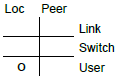
- Download
Backup local unit user accounts to an external file. The file is downloaded to management PC.
- Open file upload
Restoring user accounts from an external backup file.
Factory settings
The unit offers several factory reset options. Select the desired action and press the Reset button to perform the action.
- Link settings (both Local and Peer unit)
The entire set of parameters from the Link Settings menu tree is affected (except user credentials).
- Local logs and history
Local logs and history (graphs) will be cleaned. Unit will reboot.
- Local switch settings
The entire set of parameters from the Switch menu tree is affected (except user credentials).
- Local link, switch and user accounts configuration
The entire set of parameters from the Link Settings and Switch settings menu tree is affected including user credentials. The execution of this level of Factory settings can also be invoked by pressing the HW button before turning on the unit power. For details, see the Section 1.4.5, “HW button ( S )”.
- Local Total purge
Reverts the unit to its original state – as it was shipped from the factory. SW feature keys are also deleted.
| Warning | |
|---|---|
All configuration items, user accounts, SW keys, measured values and system messages (logs) will be irreversibly deleted. This task takes a few minutes to complete. Do not interrupt the power supply during the operation. |
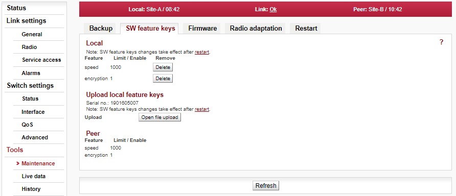
The sub-set of unit parameters is affected by use of SW feature keys. Those can be purchased together with the unit or later at E-shop or by a special agreement – see Section 1.7, “Ordering codes” for more details
Several SW feature keys limit data transfer speed [Mb/s] and/or other functionality of the unit. Each SW key is generated for specific S/N of the unit and the purchased feature. Once installed, a specific feature or function of the unit is allowed. Feature keys could be erased or upgraded anytime. To be able to manipulate SW keys, it is necessary to access directly the management system of the relevant unit – use the IP address of the relevant unit.
Speed of the transferred data is determined by a combination of the radio channel bandwidth (parameter Bandwidth [MHz]) and modulation order (parameter TX modulation). SW key limiting the data transfer speed enables only certain combinations of the channel bandwidth and modulation. The maximum data transfer speed is typically slightly higher than declared by the SW key speed value. SW keys for capacity could be different for each side of the link – for example if the link is expected to be configured for asymmetrical capacity.
When installed, the SW key is activated after the unit restart. The unit can be restarted using the Tools > Maintenance > Restart. Choose the Restart mode – warm.
Local
Shows current status of installed SW feature keys on Local unit.
- Feature
The functionality controlled by the SW keys:
Speed
TX power
Sync Eth
Encryption etc.
- Limit / Enable
The numeric value set by the SW feature key or the indication of key activity (value ‘1’ means the key is active).
- Remove
The specific SW feature key can be deleted using the Delete button. The parameters controlled by this key are reset to their default values after the unit restart. Only local keys could be deleted.
Note Before deleting the SW feature key it is recommended to configure the link such a way that it does not require this key.
Upload local feature keys
SW feature keys are installed into the unit from binary files. Installed keys are activated after the unit restart.
- Button ‘Open file upload’
Opens a dialog for the SW feature key binary file selection.
Note Use the file as it is (do not unpack).
Peer
Shows current status of installed SW feature keys on Peer unit.
Items ‘Feature’ and ‘Limit / Enable’ have identical meaning as for the local unit.
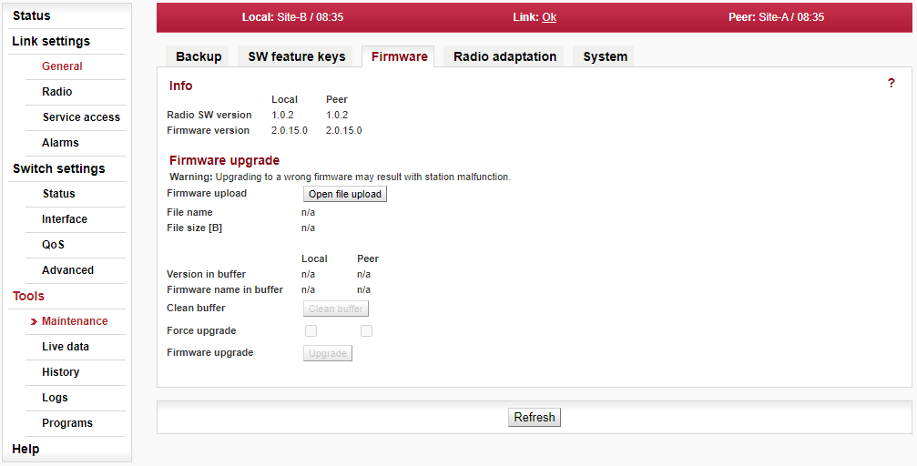
New firmware for microwave units is released regularly. New firmware versions may contain newly implemented functions, bug fixes, and security updates. The firmware is available for free download on the manufacturer’s website. The user interface allows simultaneous update of both units. Both units should have the same firmware version installed.
If the user needs it, the integrity of the downloaded file can be checked. In addition to the firmware package file (e.g. ray3-fw-2.0.23.0.cpio), a file containing the SHA-256 checksum of the firmware package (e.g. ray3-fw-2.0.23.0.cpio.sha256) must be downloaded. Checking the integrity of the firmware package then consists of comparing the locally created checksum of this package and the checksum downloaded from the website. Both checksums must be identical.
Example of creating a checksum in Microsoft Windows – Power shell:
Get-FileHash -Path "C:\Users\admin\Downloads\ray3-fw-2.0.23.0.cpio" -Algorithm SHA256
Example redirecting the checksum to a file:
Get-FileHash -Path "C:\Users\admin\Downloads\ray3-fw-2.0.23.0.cpio" -Algorithm SHA256).Hash | Out-File "C:\Users\admin\Downloads\ray3-fw-2.0.23.0.cpio-local.sha256"
Info
- Radio SW version
Information about the Software Defined Radio (SDR) version on the Local and Peer units.
- Firmware version
Information about the current firmware package version on the Local and Peer units.
Firmware upgrade
- Firmware upload
Open file upload – opens a dialog for uploading firmware package to the unit buffer. Only after firmware has been prepared in the buffer, can you perform the actual upgrade.
Note Use the file as it is (do not unpack).
- File name
Name of the uploaded firmware file.
- File size [B]
Size of the uploaded firmware file (in bytes).
- Version in buffer
Information about firmware version prepared in the buffer for installation into the unit (Local, Peer). This firmware must first be prepared in the Firmware upload section (see above).
- Clean buffer
You can use the Clean buffer button to delete prepared firmware package in the buffer.
- Force upgrade
Force mode blocks all safety and compatibility checks and may result in breaking your unit.
Important You should not use force mode until instructed to do so by the technical support.
- Firmware upgrade
Use the Upgrade button to perform the firmware installation.
Warning Installing the firmware takes about 45 seconds (including reboot). During this time, transmission of user data is interrupted. Do not interrupt the power supply during firmware installation!
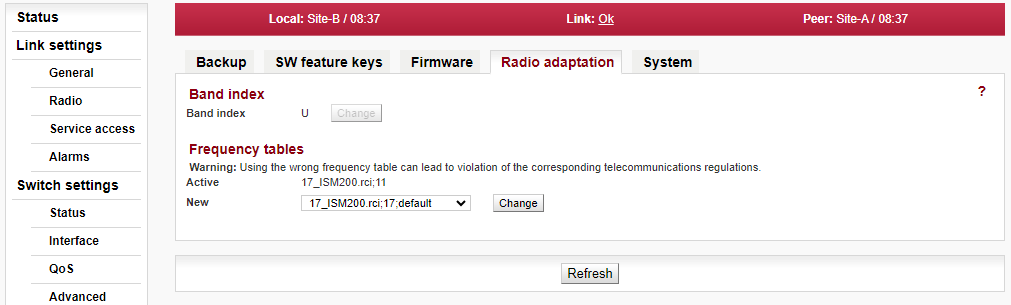
Band index
- Band index
Band index displays radio channel assignment of local unit transmitter (TX) for L (Lower) or U (Upper) part of the frequency band.
- Change button
Applies only for 17 GHz and 24 GHz links (where hardware of each unit is universal for the entire frequency band). Change button changes the band index (L -> U and U-> L). If units are linked together both Local and Peer units are changed in the same time.
Note Changing band index is allowed only in symmetric mode (i.e. TX bandwidth is the same as RX bandwidth).
After restoring factory settings Band index is set to its pre-defined state L or U as typed on Product Label.
Warning When the radio band index is changed, the “Link settings” menu parameters of each unit are reset to default values except login / password details.
Frequency tables
The microwave link contains one or more frequency tables (called rcinfo). These tables contain the following information:
List of available bandwidths and modulations.
Assignment of frequencies to the channels and the names of these channels. These channels are used to configure radio parameters of the link (see screen Link settings > Radio).
Default values of radio parameters.
A set of radio parameters, needed for the ATPC operation.
Just one frequency table can be active in a given time. Tables can not be modified by a user or combined together. If a different radio parameters or channel names has to be used (for example due to new telecommunication regulation), please contact your supplier and ask for a proper FW with the frequency table for your situation.
- Active
Name of the currently used frequency table in format <name:version>.
- New
Select a new frequency table. Available tables are displayed in format <name:version>. Use the Change button to change the table.
Warning Using the wrong frequency table can lead to violation of the corresponding telecommunications regulations.
Note Later versions of the same frequency table allow a wider functionality of the unit. Thus it is recommended to keep active the latest version of chosen frequency table.
Compatibility
- Unit ’24S’ compatibility (formerly ‘Unit S mode’)
This parameter is available only for newly deployed 24 GHz units without the ‘S’ label in Product code (i.e. ’24S’) – as visible on Product label and in Ordering codes. When “active”, the unit behaves like the unit ’24S’ (it can establish a link only with another ’24S’ unit). For a link between the units without the ‘S’ label, this compatibility needs to be disabled (“off”). The unit reboots after changing this parameter.
Note Used only if a combination of different hardware variants of units have to be used to set up the link together. Wrong setting of compatibility causes the link is not established (both units remain in status ‘Connecting’). For more info see chapter Troubleshooting in the product manual, the topic ‘Setting up a link between RAy3-24S and other hardware variant of RAy3-24’.
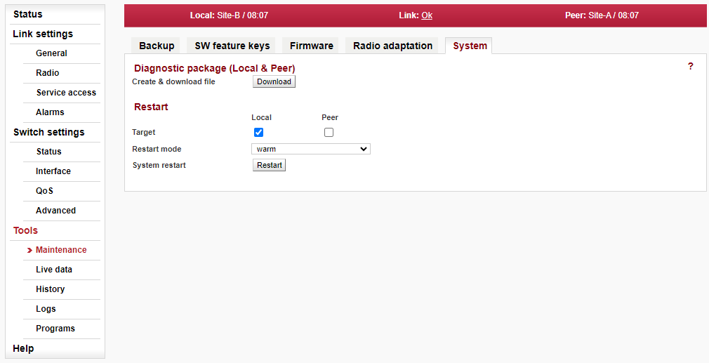
Diagnostic package (Local & Peer)
To facilitate communication with the technical support you can create an archive file with detailed information about the unit. If connection with Peer unit is active the diagnostic information from both units are saved.
- Create & download file
Saving a file with information about the unit (Local and Peer).
Note This task takes a few minutes to complete.
Restart
- Target
Chose the unit(s) to be restarted: Local or Peer or both.
- Restart mode
Chose the type of the restart:
Warm — Reboot only management system and web interface.
Cold — Restart the whole unit as if power was removed.
- System restart
Pushing the “Restart” button performs the selected restart.
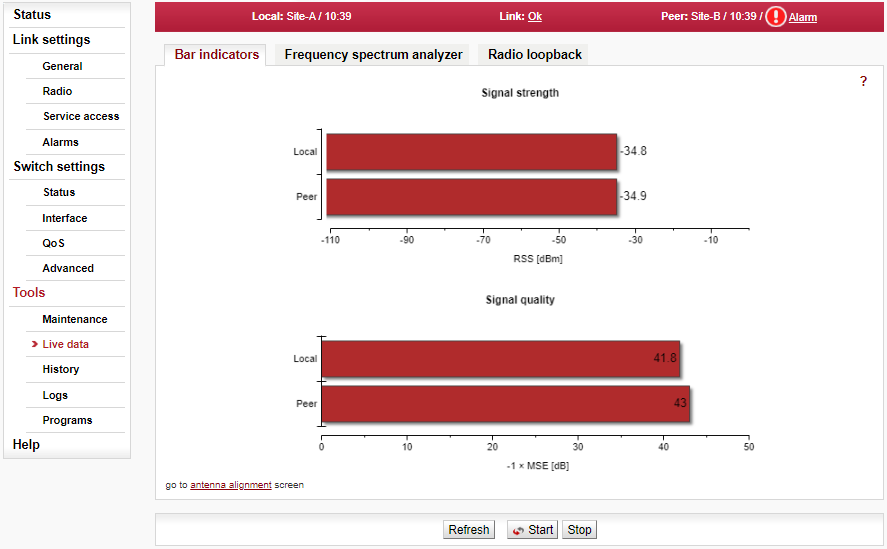
Graphical indication of RSS and MSE.
- Refresh
One-time update of displayed values.
- Start, Stop
Start button starts automatic update of displayed values with a period of 1 second. Stop button stops refreshing of both graphs.
- Antenna alignment
Link “go to antenna alignment screen” activates Antenna Alignment Tool (black page ).
The Antenna Alignment Tool supports interactive antenna alignment. RSS and MSE are displayed for both local and peer unit. A selected value can be indicated in large font and acoustically. Values are refreshed 10× per second.
When performing antenna alignment, both ATPC and ACM/ACMB functions should be disabled; their automatic behavior interferes with the alignment process which is based on finding the maximum signal strength.
The tool is accessed via management IP address e.g. http://192.168.169.169/tk for standard Ethernet ports, and via http://172.17.17.17/tk for connections using USB/WiFi or USB/Eth. The Antenna Alignment Tool does not require user authentication.
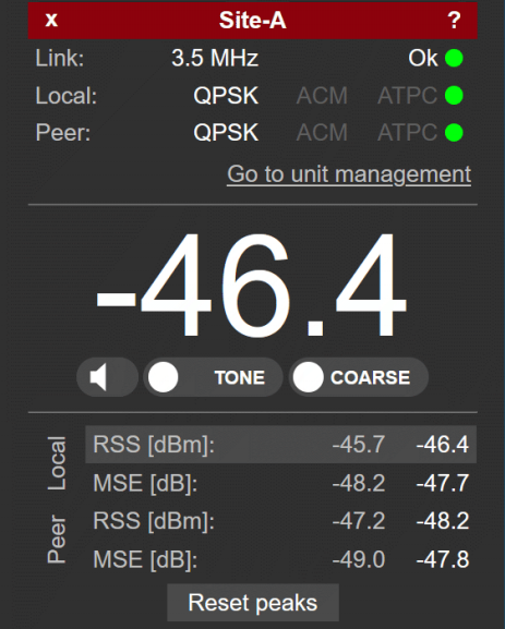
- Red strip
(top of the page)
+ — Increases the number of displayed parameters
x — Decreases the number of displayed parameters
text — Local Station name (e.g. Site-A)
- Link
3.5 MHz Ok — Channel width
Link connected (green icon).
The Peer values (see below) are visible when the connection between Local and Peer unit has been established.
- Local, Peer
from QPSK_S to 4096QAM or from 2PSK_BW/4_S to 128QAM — Current modulation of the TX signal.
ACM/ACMB, ATPC — Status of ACM/ACMB + ATPC (red color warns at least one of those is enabled).
- Go to unit management
Link to the full configuration interface of the microwave unit; user authentication is required.
- -46.4
Actual RSS [dBm] or MSE value. The selected value is chosen by clicking/tapping on the respective value below the main display.
- Exclamation icon !
An exclamation icon is displayed when either Local or Peer unit has ACM/ACMB or ATPC enabled. Those should be both disabled; they can affect signal strength.
- Icon of speaker
Acoustic indication for local RSS value ON/OFF. The TONE or BEEP signal is supplemented with voice output every 10 seconds, notifying signal strength.
- TONE / BEEP
Select the sound generated. The better the signal, the higher the frequency. The acoustic indication is linked to the value on the main display. If a WiFi connection is used to access Antenna Alignment, the ‘noise’ audio signal is used to notify low quality or low stability of the WiFi signal.
- COARSE / FINE
Choose the scale of acoustic indication.
COARSE — for approximate alignment. Range of tones (or frequency of beeps) is equal to -100 to -30 dBm.
FINE — for a more precise alignment. Range of tones (or frequency of beeps) is equal to ±10 dBm from the value sampled at the moment when the FINE button was pressed).
- RSS, MSE
Values RSS and MSE for local and peer unit (4 values in total):
First column — Best values recorded
Second column — Current values.
The value to be displayed on the main display is selected by a tapping/clicking on the respective value.
- Reset peaks
Best values history is cleared.
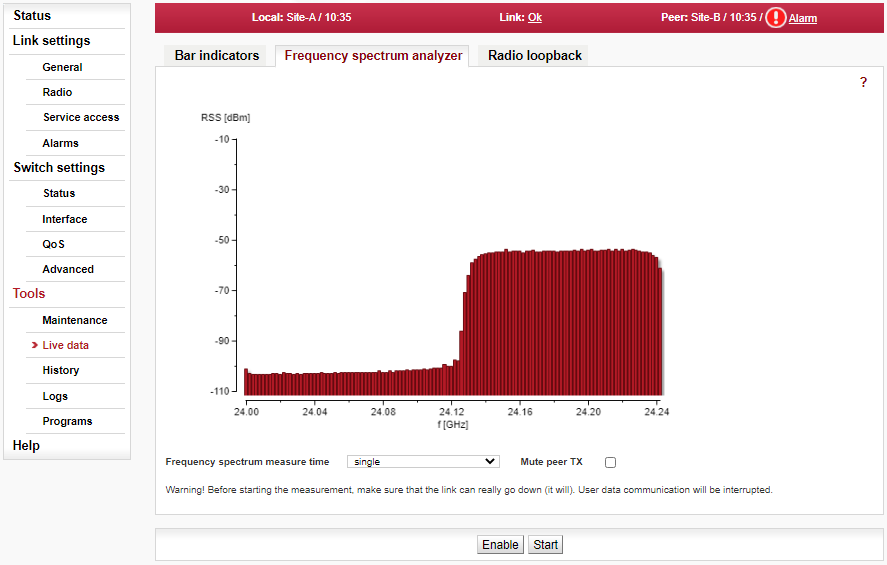
A very useful tool for identifying in-band interference and locating a free channel. It is not a full-blown spectrum analyzer as it scans the spectrum with 2 MHz channel resolution. The accuracy of measured results is given by the accuracy of measuring RSS.
- Enable
Opening analyzer functions.
- Start
Interrupts communication on the link and starts scanning frequencies in the band.
- Spectrum measure time
Selection of measurement length in range:
- Mute peer TX
The deactivation of Peer station transmission during measurement. single sweep … up to 15 min
| Note | |
|---|---|
Single sweep takes about 2 seconds for the whole band scan in 17 or 24 GHz (only 200-250 MHz wide). For licensed bands and for 80 GHz band it takes adequately longer – according the width of RX and TX parts of the band. The link is automatically re-established after it is finished. |
| Warning | |
|---|---|
Running spectrum measurement causes interruption of user data flow between stations! |
Interruption of the scan before selected measure time can be achieved anytime by visiting any of the Link menu settings and select Refresh. This restores the configuration connection (message Peer: n/a).
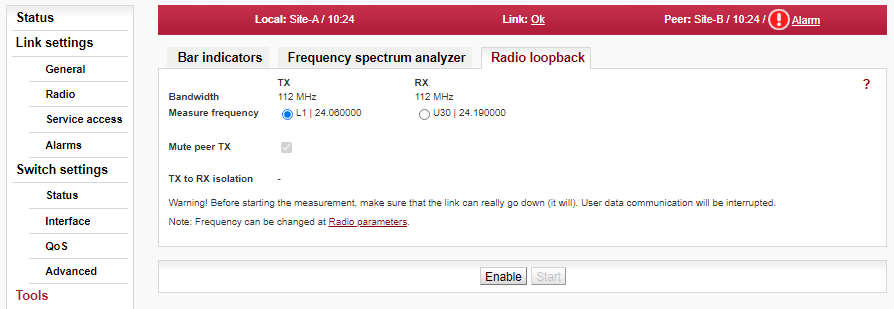
Radio loopback measurement serves as a check of quality of the antenna connection to the microwave unit and the quality of the antenna itself. Only available for the 17 GHz and 24 GHz units. The function provides indicative measurement of an antenna parameter CPI (Cross-Port Isolation). It is done by evaluation of strength of the signal in other (RX) polarization received from its own transmitter (transmitting in TX polarization, 90 degrees from RX polarization). The lower the strength of unwanted signal returned by the antenna received, the better the antenna quality for Cross-polarization data transmission used by 17 and 24 GHz units.
| Warning | |
|---|---|
User traffic is interrupted during command execution! |
- Bandwidth
Channel widths used for transmitting.
- Measure frequency
By default, the Radio loopback is measured with the current frequency of the transmitter. Measurement can be performed with the frequency of the receiver. Both results may differ slightly because the antenna parameters are frequency dependent.
- Mute peer TX
The deactivation of Peer station transmission during measurement (not to interfere with the measurement).
- TX to RX isolation
The result of the Radio loopback measurement is given as the ratio between the levels of the transmitted and received signal. The ratio is given as a logarithmic value in [dB]. The higher the number, the better the antenna quality. Here are the thresholds for evaluating the results:
less than 40 dB – insufficient
from 40 dB to 45 dB – reasonable
more than 45 dB – good
Note Possible reasons for isolation ratio lower than 45 dB are listed below. They are ordered according the probability of occurrence. Typical methods of repair are described as well:
Silicon grease in the waveguide => clean the antenna waveguide and the neck of the unit
Antenna for another frequency band => check the type of antenna and replace it with a suitable one
Frozen (dewy) antenna => after climatic conditions improvement everything returns to original values (antenna heating would eliminate that – quite useful in mountainous areas)
Reflective (metal) surface near the antenna (even outside of the Fresnel zone) => change of antenna position
Mechanically damaged antenna dish or radome => inspection of the antenna, cleaning or replacement of the radome
Lost mirror at the end of a waveguide inside the antenna => inspection of the antenna interior, its repair or replacement
Damaged polarization transducer inside the unit => repair of the unit at the manufacturer (this never occurred, yet)
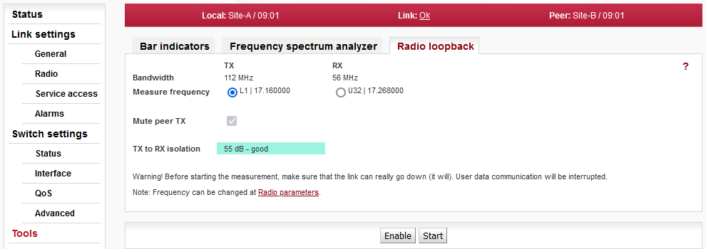
The unit continuously stores information about the values of important variables. Stored values can be viewed using three methods – Thumbnails, Viewer and Data.
Preview all values for the last 24 hours. Click on a thumbnail to open the viewer with a chart.
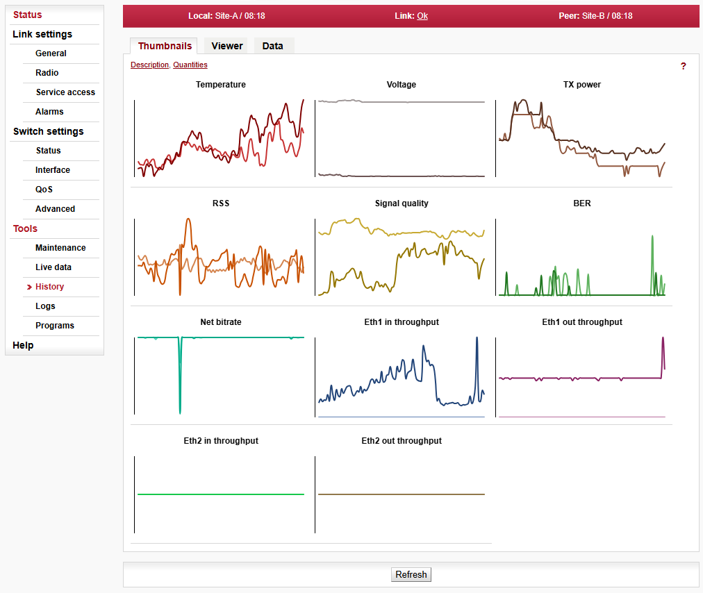
- Temperature
Instantaneous value of temperature inside the unit. Measured on the modem board.
- Voltage
Instantaneous value of unit supply voltage.
- TX power
Instantaneous value of transmission RF Output power.
- RSS
Received signal strength.
- Signal quality
Signal quality of the received signal. It is negative value of Mean Square Error (MSE, the inverse to often used SNR – Signal to Noise Ratio).
- BER
Instantaneous bit error rate on link.
- Net bitrate
Instantaneous transmission capacity.
- Eth1, Eth2 in throughput
Instantaneous speed (20s average) of incoming user data on the user Ethernet port.
- Eth1, Eth2 out throughput
Instantaneous speed (20s average) of outgoing user data on the user Ethernet port.
- Dual channel
In the case of Dual channel operation, the parameters of both channels are displayed. The parameters of the second channel are marked with index 2 (TX power 2, RSS 2, Signal quality 2, BER 2).
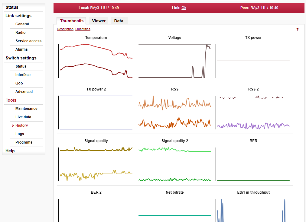
Detailed graphical view of one or two selected values for the given interval. You can choose to view data from Local or Peer or both.
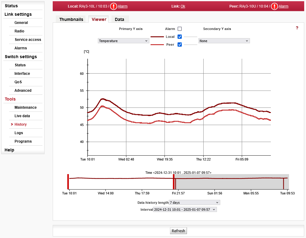
- Data history length
The values are saved in the following resolutions and history lengths:
7 days, Resolution 1 minute, length of history 7 days
30 days, Resolution 15 minutes, length of history 30 days
180 days, Resolution 1 day, length of history about 180 days- Interval
Selecting time interval to be displayed from the currently selected history length. Each history length can have multiple time intervals to choose from. Time interval represents data history in a continuous time. In other words, new time interval appears when backward time jump is detected. On the other hand, when forward time jump is detected, it is represented as a blank spot in the graph and as a slope in the slider (slope does not appear when data values of the current series are close to their minimum).
- Primary Y axis
Selecting one of the observed values:
Temperature, Voltage, TX power, RSS, Signal quality, BER, Net bitrate, Ethernet in throughput, Ethernet out throughput
- Secondary Y axis
Selecting a second value:
None, Temperature, Voltage, TX power, RSS, Signal quality, BER, Net bitrate, Ethernet in throughput, Ethernet out throughput
- Alarm
Enables the display of alarms, if there were any.
Numerical view of all values.
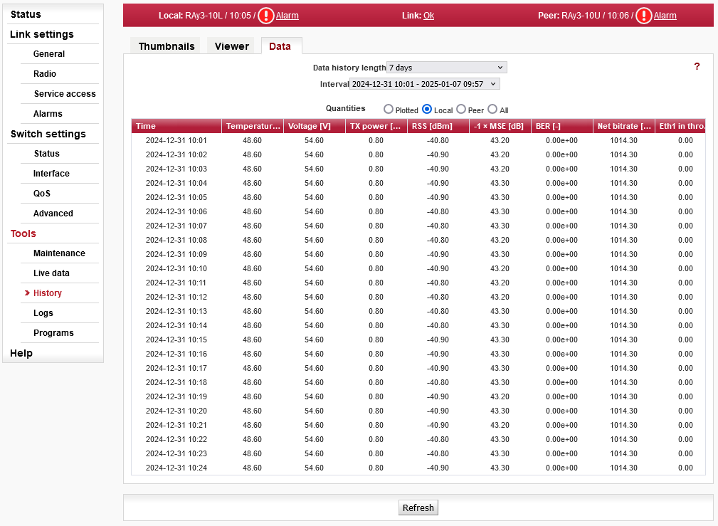
- Quantities
Detailed graphical view of values for selected interval.
Plotted — Shows only the values that are selected for the graph.
Local, Peer, All — Shows all logged values. Filtering of values from local, remote or both.
- Data history length, Interval
See explanation of those in Viewer section above.
Shows internal unit logs. Individual tabs allow total or filtered view.
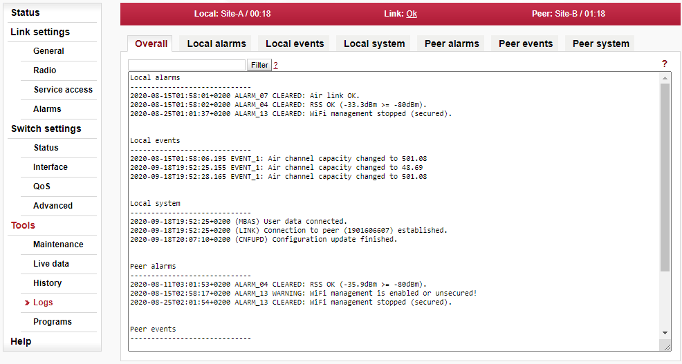
When you first open the screen, it is necessary to start browsing logs by pressing the Refresh button.
Maximum length of displayed logs is 250 entries. If you need to display longer history, use CLI interface instead.
- Overall
Displays the last 3 records from all types of logs.
- Local alarms, Peer alarms
Alarms from Local or Peer unit.
- Local events, Peer events
Events from Local or Peer unit.
- Local system, Peer system
System events from Local or Peer unit.
- Filter
Listings of all logs can be filtered. Filtering string is entered in to the upper left corner window and Filter button is pushed. For example, you want to know when the configuration of the unit was modified: On the Local events screen, enter
Configurationand hit Enter. Plain text or regular expressions can be used for filtering (JavaScript format).
The Ping tool allows sending ICMP pings to a selected address
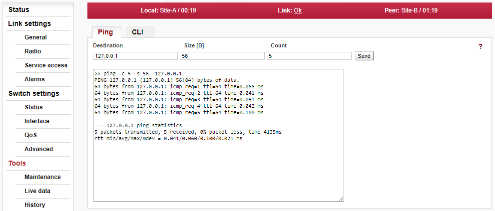
- Destination
Destination address in dotted decimal notation. The default address 127.0.0.1 is the localhost address – i.e. the unit itself.
- Size [B]
Length of sent data 7 to 1500 bytes, 8 bytes of the header will be added.
- Count
Number of sent pings.
Start the test by clicking on Send. The period for sending pings is constant: 1000 ms. The result is displayed in the text window.
Web interface for executing non-interactive scripts and programs.

- Manage custom commands
Using “Open file upload”/”upload” the user can upload scripts to the unit. The uploaded file can be either a single shell script with extension .sh (e.g. my_script.sh) or package with multiple scripts with extension .tar.gz or .tgz created using tar.
“Delete all” removes all custom scripts from the unit.
Custom scripts are located in /home/shared/bin.
- Custom commands
A custom script can be selected here and initial comments/help is shown.
- CLI commands
A CLI command can be selected here. You can use cli_help for listing all CLI commands or <command> –help to obtain detailed help on a selected command.
- Command
Command line for writing commands with parameters. You can use any non-interactive program/script according to your permissions. Command is executed by pushing the “Run” button.
- Format of custom scripts
Custom scripts must be a shell script with preamble #!/bin/sh and extension sh.
Blocks of lines beginning with the comment sign (#) after preamble are considered to be help and are listed when the script is selected in the web interface.
Scripts should not be interactive as there is no possibility to send a response from the web interface. All script options should be implemented as parameters.
Syntax should be valid for interpret shell ash from BusyBox v1.20.1.
- Example of custom script
#!/bin/sh
#script checks if service with the same name or vid already exists
#if not creates a new entry in VTU with given VID
#
#  input parameters:
#      service_name - name of the new service
#      VID - vid of the new service
#
#  return values:
#      0 - ok
#      3 - bad parameter
#      5 - service already exists
#      6 - there already exists an entry with given VID
#     42 - other error

D42_NAME="$1"
D42_VID="$2"

D42N="service_data42"

error()
{
        echo "$D42N: Error: $*" >&2
}

info()
{
        echo "$D42N: $*" >&2
}

die()
{
        error "$*"
        exit 42 #error
}

# basic check if not empty
if [ -z "$D42_NAME" ]; then
        error "Bad service name"
        exit 3
fi
if [ -z "$D42_VID" ]; then
        error "Bad service VID"
        exit 3
fi

D42_FOUND=$(cli_nw_get --vtu all | grep "$D42_NAME")
if [ -n "$D42_FOUND" ]; then
        error "Service(s) with name $D42_NAME found"
        echo $D42_FOUND
        exit 5
fi

D42_VALID=$(cli_nw_get --vtu "$D42_VID" | sed -n 's/^valid=\(.\+\)$/\1/p')
if [ "pre_$D42_VALID" = "pre_true" ]; then
        error "VID $D42_VID is used"
        cli_nw_get --vtu "$D42_VID"
        exit 6
fi

D42_VALID=$(cli_nw_get --stu 1 | sed -n 's/^valid=\(.\+\)$/\1/p')
if [ "pre_$D42_VALID" = "pre_false" ]; then
        info "Creating STU entry with SID=1"
        cli_nw_set --stu 1 'label="D42_auto", port_state=["disabled", "disabled", "forwarding", "disabled", "disabled", "forwarding", "forwarding"]'
        if [ $? -ne 0 ]; then
                die "Failed to create STU entry"
        fi
fi

info "Creating service \"$D42_NAME\" with VID=$D42_VID"
cli_nw_set --vtu "$D42_VID" label="$D42_NAME" 'fid=0, sid=1, pri_override=true, priority=5, policy=false, member_tag=["unmodify", "unmodify", "tag", "unmodify", "not_member", "not_member", "unmodify"]'
if [ $? -ne 0 ]; then
        die "Failed to create service \"$D42_NAME\" with VID=$D42_VID"
fi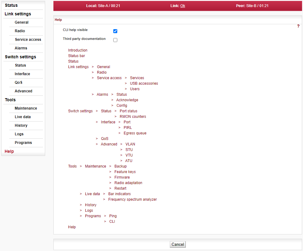
Help from Help menu
The Help screen displays contents of the embedded help. The help text is displayed in the whole configuration window. The text structure corresponds to individual configuration screens. Every item of this Help opens the specific help menu.
- CLI help visible
Allows displaying of the CLI help with examples.
Help from configuration menu
Clicking the name of the specific parameter in the configuration menu brings up the help belonging to this parameter. The help text is displayed in the pop-up window:

There is a Go to help link within the help text. It displays the whole configuration menu help:
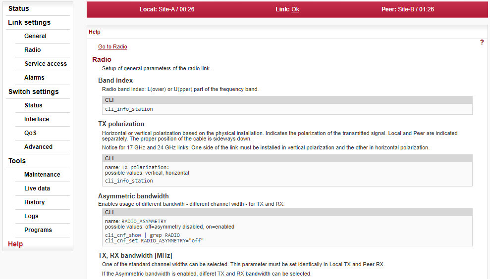
There is a link on each help screen which points to the respective configuration screen.
Clicking the question mark icon in the upper right corner of the configuration screen brings a summary help for the configuration screen in the pop-up window:
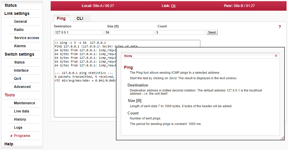
The Help window can be moved by dragging the Hints bar. Resize it by dragging the bottom corner.