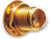
There is an SMA-jack antenna connector on the radio modem panel. Use only the respective type of connector of the respective impedance on your antenna cable : SMA-plug, 50 Ω. It is recommended to use antenna coaxial cables like this: RG58 up to 10m, RG213 up to 25m, H1000 for longer.
| Important | |
|---|---|
A radio modem may be destroyed if an antenna or dummy load antenna is not connected. |
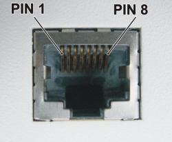
Ethernet connector RJ-45 for 10BaseT and 100BaseT fully matches the standard of Power over Ethernet IEEE802.3af.
The radio modem recognizes a standard or crossed cable and adapts itself automatically.
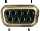
There are 2 possibilities for the power supply:
AUX – via RS232 DSUB9 connector, using pins 5 and 9 (see Section 3.2, “Serial interface”). Voltage 10.5-30 V, nominal 13.8 V.
To connect the power supply via RS232 connector, can be used REPWR adaptor.
PoE – via Ethernet connector RJ-45 using PoE standard IEEE802.3af. Voltage 38-57 V. Common version of supplying:
plus to pins 4+5
minus to pins 7+8
the polarity can be inverted also
For other options with PoE adapter see the standard IEEE802.3af.To connect the power supply via Ethernet connector, can be used Passive PoE injektor.
| Important | |
|---|---|
Only ONE of the above power supply options can be used ! |
Examples and details in Chapter 6, Radio modem installation.
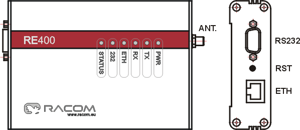
Key to LEDs
| PWR |
|
| TX |
|
| RX |
|
| ETH |
|
| 232 |
|
| STATUS |
|