Racom radio modems feature robust, metallic casing. They are used in different applications in different environments, ranging from air-conditioned offices to heavy-industry plants.
Information in this chapter describes the standard method of installation, used in common industry applications. It is based on regulatory standards which apply to the equipment and on the long-term experience of our engineers. If your network is large and your application complex, we recommend the network design to be done by one of our partners or directly by Racom. Every network design should begin by field measurements of the signal strength and quality and by careful evaluation of conditions for propagation of radio waves in the area.
Every radio device has to meet conditions for operation in the given frequency range in the respective country and the operator is responsible for the compliance.
A reliable operation of a radio modem requires a proper connection to the data-terminal equipment serviced, the antenna has to be properly installed and connected to it and a proper and safe power supply has to be used. The mounting and the optional housing has to correspond to the environment and must not harm the radio modem performance.
The description of all interface connectors can be found in the Chapter 3, Connectors.
Optimum installation of the antenna is influenced by a number of factors. The topology of the radio network, the separation of radio points, the terrain profile between them, and conditions for signal propagation all influence the type of antenna to be used and where it should be located. Sometimes the appearance of the structure on which the antenna is to be located and the possibility of its damage in publicly accessible places should also be taken into consideration. Generally it can be said that for point-to-point type connections directional antennas are used, and for more remote points and points with a poorer signal multilink directional antennas with greater gain are used. The height of the antenna above ground level may improve the quality of the signal. The standard height of approx. 5 m can be increased severalfold, but always in consideration of the length of the antenna lead, because each coaxial cable used has its own defined attenuation. For longer leads coaxial cables with lower attenuation are used and generally these have a larger cross-section, worse mechanical properties and are more expensive. When using external antennas we recommend protecting the radio modem with overvoltage protection on the coaxial cable.
We recommend to use vertical polarization for all radio modem networks.
Racom radio equipment in typical installations comply with applicable standards for human exposure to RF electromagnetic fields, namely with standard EN 50385: 2002. The minimal safe distance is ensured by the antenna position on a mast. When special installation is required, the conditions of the standard above have to be met. The distance between the persons and antenna minimal 5 m comply with applicable standards for human exposure of general public to RF electromagnetic fields, namely with standard EN 50385: 2002. It is valid for all power levels and all antenna types which firm Racom provides.
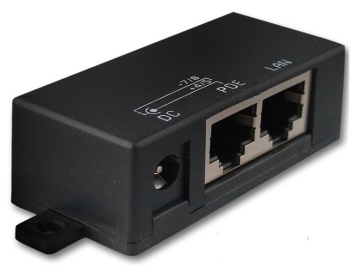
A power supply has to meet technical specifications of the equipment powered, see Section 4 Table of Technical parameters. Radio modem can be powered either over the Ethernet interface according to the PoE (Power over Ethernet) standard or over the SCC (RS232) interface by DC voltage 10.8-30V (13.8V nominal). When powering over SCC we recommend one of the MORSE power supplies, e.g. MS2000, which were specially designed for supplying of radio modems. MS2000 can provide seamless switching to a backup battery while monitoring its state and charging it in an optimum way. When using PoE, we can also recommend a RACOM PoE power supply which includes battery backup option.
The following pictures show the four possible variants of power supply.
Fig. 6.3: Supplying power over the SCC interface, using a REPWR adaptor and P.S. with battery backup
The layout of installation showed at ver. 4, i.e. when the radio modem is placed up on the mast (or close to it), provides the valuable advantage of having a short antenna feeder (see section Antenna installation). Remember that the ethernet cable has to meet the PoE standard requirements (IEEE802.3af).
Power adaptors for RE400
The Data Terminal Equipment, a programmable controller, a PC or any other device communicating over the radio network, has to be connected to the router by a data cable to the serial or the Ethernet interface according to the respective standard. These interfaces are described in detail in the chapter Connectors.
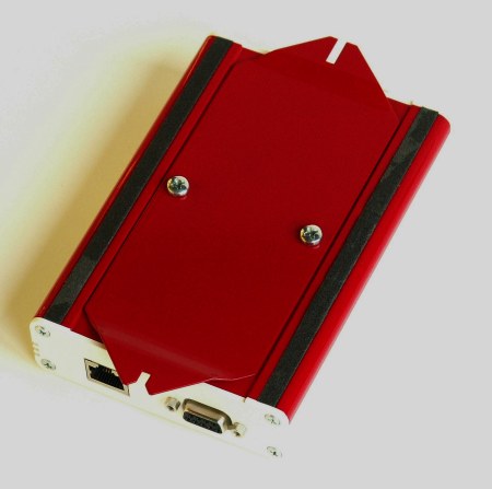
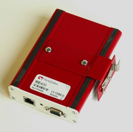
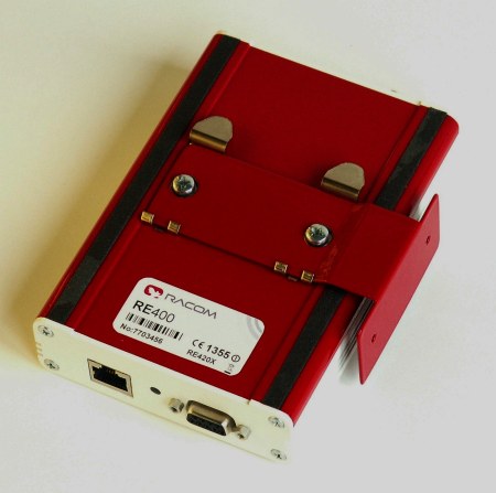
Radio modem can be either attached by screws to a mounting plate or simply clipped to a DIN rail. In both cases, the body of the radio modem can be positioned (with respect to the mounting plane) either horizontally (i.e. sitting on the flat base of the casing) or vertically (i.e. sitting on the narrow side). That means there are four basic variants of mounting. The variant for which the mounting accessories are delivered is indicated in the manufacturing code and can be requested in the order by specifying the code, see Section 5.2, “Labelling of Radio Modems”. When no mounting preference is given, the basic variant “D” (DIN rail, horizontal) will be delivered.
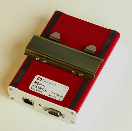
All the dimensions and detailed drawings relevant for mounting can be found in the Section 5.1, “Dimensional Diagram”. In a typical installation for industrial applications the radio modem is mounted into an IP54 cabinet together with the power supply, the backup battery and the surge protector.