Firmware version 2.1.x.x is not compatible with older versions 2.0.x.x. Older fw needs to be upgraded with the new version 2.1.x.x, see Section 2.7, “Firmware upgrade”.
There are 3 possible operation modes:
Main mode – mode of a standard operation
Service mode – mode for firmware download
Bootloader mode – mode for downloading bootloader
Main mode is a standard operating mode where the radio modem works as a transparent bridge on the Ethernet interface or as a transparent link (bus) on the serial interface. Main mode is operated after approx. 20 sec. from switching on the supply voltage. The deblock mechanism can be activated after a short-time break and can stretch this time. Main mode is indicated by LED STATUS – green colour 2 sec. ON and 1 sec. OFF.
When button RST is pressed for 10 sec. during Main mode, the STATUS LED changes its colour to yellow and the parameters are set to default values. After the next 15 sec. default values are saved and the radio modem goes back to Main mode working with default values and IP address 192.168.1.2 hereafter.
Frames are transmitted to the opposite side of the radio network to an application through the same interface (RS232 or Ethernet) as they have been received.
The data received through SCC is loaded into buffer of depth 5 packets and subsequently sent to RFC.
A packet received through RS232 is closed when its size achieves a value set in the MTU parameter, or after a pause, which is equal to the parameter Idle. Afterwards it is immediately transmitted to the RF channel (neither CDMA nor TDMA RF channel access). All radio modems which receive this packet transmit it to their serial interface. The network works like an RS232 bus, i.e. every one hears each other, so it is suitable for “poll” type applications, when the master station polls requests to slave stations one by one. It is possible to connect more slaves behind one radio modem using an external RS485 converter.
The data received on ETH channel are sent immediately to RFC. The packet received during RF transmitting is discarded. The operating with the Repeater when the parameter NoR has a nonzero value is a exception. The input buffer of depth 1 packet is used here. It allows accept the response from ETH device connected in the short time after receiving the packet from RFC. The RFC transmitting is suspended at that time, see the article Repeated packets.
The radio modem works as a standard Ethernet transparent bridge, i.e. received frames are filtered and only frames for addresses behind the RF channel are transmitted to the RF channel. The only exception are broadcast packets which are all transmitted to the RF channel.
More information on http://www.linux-foundation.org/en/Net:Bridge.
Example:
One RE400 is connected to a LAN1 segment, the second RE400 to a LAN2 segment. IP addresses of both RE400 are not important for data transfer itself. They are used only for service purposes (setting up parameters). It is FORBIDDEN, however, to set the IP address of any radio modem to the same value of any equipment in either LAN1 or LAN2 segments.
The first RE400 connected to LAN1 processes frames as follows:
broadcast (arp req) and arp reply… — transmitted to RF channel
frame for destination addresses within LAN1 segment — discarded
frame for destination addresses within LAN2 segment — transmitted to RF channel
Before sending to the radio channel the checksum is calculated. After data is received from RFC it is checked. If the CRC does not match the packet is discarded.
If station RE400 has the Repeater function switched ON then the received packet will again send another packet to the RF channel. The packet received from the RF channel is also sent to SCC or to the ETH port. In the radio network it is also possible to use more Repeaters without danger of cycling packets. When switching on function Repeater it is necessary to enter the number of Repeaters in the network into parameter Number of repeaters (NoR). Parameter NoR is set in the same way in all radio modems of the network.
Parameter Number of repeaters switches on protection mechanisms which prevent collisions with packets sent by the repeater. After transmitting or receiving a packet from RFC further transmission is blocked for the required period to prevent a collision with a packet sent by the Repeater. After transmitting or receiving a packet from RFC recepit of its copy is checked and discarded.
These measures are not active when parameter NoR is zero, i.e. in a network without Repeaters.
There is built in compression on the RF channel. Its final efficiency depends on the data structure, of course.
It is possible to set a threshold on the radio channel from which transmitted packets begin to fragment. The receiving modem transmits a packet to the interface only when all fragments are received successfully. This also applies in a Repeater for transmission of a packet to the RF channel.
From fw 2.1.3.0 the fragmented packets are processed in Repeater in the different way. This caused the acceleration of communication but simultaneously the incompatibility with the older versions 2.0.x.x. These older firmware is to be replace by the version 2.1.3.0 or better newer one of the serie 2.1.x.x, see Section 2.7, “Firmware upgrade”.
In the case of good conditions for communication on RFC remote access to radio modem RE is an available option. Insert the IP address of the remote modem RE into the www browser attached by Ethernet cable to the RE modem. Leave cursor in the address line and press Enter. We can read and save configurations in the remote modem. Typical reaction time is 20 to 40 sec.
This function is not generally guaranteed because the http protocol is not optimised for work in slow networks. In the case of a slow response from the radio channel the TCP protocol adaptively extends timeout up to tens of seconds. In addition a PC running Windows generally has other protocols installed on the ETH channel which load or worsen communication conditions.
These modes are used for firmware upgrades (Section 2.7, “Firmware upgrade”): Service mode for firmware downloads, Bootloader mode for bootloader downloads.
Switching to Service mode: approx. 2 sec. after switching on power press the RST button for a few seconds. Service mode is indicated by the yellow STATUS LED flashing every 1+1 sec.
Switching to Bootloader mode: keep RST button pressed while switching on the power for approx. 3 sec. Bootloader mode is indicated by quick flashing of the yellow STATUS LED.
Both Service mode as well as Bootloader mode use 192.168.1.1. IP address.
Two radiomodems having the same address must not be in the common network neither radio nor ethernet.
Parameters of each radio modem are set during production with default values : IP address 192.168.1.2, mask 255.255.255.0. It is strictly forbidden to connect a radio modem to LAN before setting up the appropriate IP address and mask. (The default IP may already be in use in the LAN and address collision can occur)
Do not switch on more than one radio with default settings at any one time ! Only switch on the next one after setting and storing IP parameters in the first one.
In default mode radio modems use the same address 192.168.1.2 and communication amongst themselves thus disturbs IP communication between the PC and configured radio modem.Interconnect the ETH interface of the radio modem with your PC. A standard Ethernet cable should be used.
To connect the power supply, either PoE (Ethernet interface) or AUX (SCC interface) – more Section 3.4, “Power supply”, LEDs PWR and ETH should light. After approx. 20 sec. booting of radio modem is finished and the STATUS LED starts flashing green.
To set the IP address and mask of your PC in order for it to be ready to communicate with the default IP of the radio modem. A ping may be used to check that the connection works properly. Read more in Appendix A, Appendix.
Start www browser (e.g. Internet Explorer) in your PC and insert 192.168.1.2. address in the command line instead of internet address.
Settings menu is displayed. Here it is possible to set all parameters.
Select a unique IP address of each radio modem within the network. This address is not used by the connected technology, however, it is required for configuration and testing.
Individual parameters may be set (see Section 2.4, “Radio modem configuration”). Configuration can be saved into the radio modem using
Saveor into a file usingSave to file.When the IP address is changed and configuration is saved into the radio modem, the connection between your PC and radio modem will be lost. The next configuration is only possible after inserting a new IP address into the www browser. If a new IP is out of the mask of your PC, the IP address of your PC needs to be changed as well (see Appendix A)
When configuration is ready and saved the radio modem is ready to operate in your network.
Before configuring the next radio delete table Art (Start, Run, arp -d) in the PC. Table arp contains a pair of IP addresses 192.168.1.2 and MAC addresses of the radio modem. Another pair must be created for the next radio modem.
When basic parameters are set (prior to starting the application), it is recommended to test the radio connection among radio modems using a Ping in the Diagnostic menu, see Section 2.5, “Diagnostics”. An ordinary ping application from Windows, for example, may be used as well. Don’t forget to connect the antennas, see Section 3.1, “Antenna”.
Communication with the application is indicated by LEDs as described in Section 3.5, “Indication LEDs”.
ON LINE
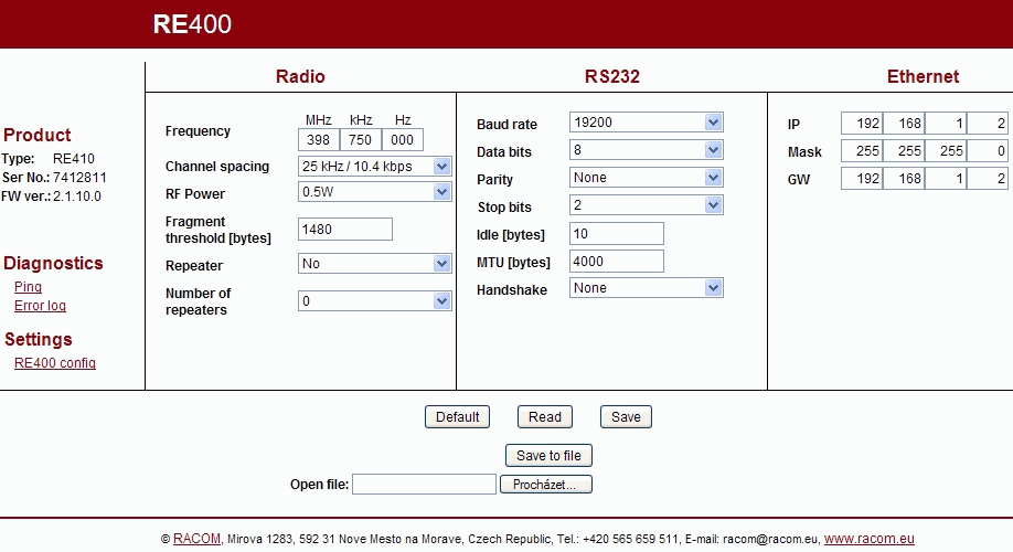
The radio modem is connected to your PC as described in Section 2.3, “First start of radio modem” and its parameters can now be set:
| Product |
| ||||||||
| Diagnostics |
| ||||||||
| Radio |
| ||||||||
| RS232 |
| ||||||||
| Ethernet |
| ||||||||
| Executive buttons |
|
OFF LINE
Parameters of radio modems can be configured off line using the web page:
http://re400.racom.eu
Using this page you can create a .cnf file that can later be downloaded into the radio modem or you can view and modify parameters already saved in a file. The download is made in two steps – load it into Configuration menu using the button Open file and save in the radiomodem using button Save.
The configuration file may be edited directly as well:
     IP=192.168.1.47                    BAUD=19200
     MASK=255.255.255.0                 DBITS=8
     GW=192.168.1.47                    PARITY=0
     TX_FREQ=402125000                  SBITS=2
     RX_FREQ=402125000                  IDLE=10
     SPACING=1                          SIZE=4000
     RFPWR=0                            HANDSHAKE=0
     REPEAT=0                           FRS=1480
     REPEAT_NO=0
Note: Check whether the set frequency is within the range for the specific type of modem; it doesn’t work for off line configuration.
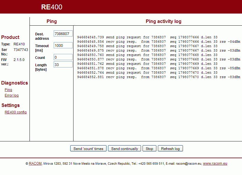
Pings are used for testing response times and signal strengths from remote radio modems.
Ping address: 7353743 — product No. of remote radio modem
Ping timeout: 1000 — transmitting period of pings, ms
Ping count: 0 — number of pings
Ping length: 22 — length of data transferred excluding header, Bytes
Send ‘count’ times — starts transmitting
Ping countSend continually — starts transmitting pings continuously – a few of seconds later the screen refreshes automatically. For next refresh use the button Refresh log.
Stop — stops transmitting
Refresh log — updates the
 Ping activity
          log
Ping activity log — standard information + RSS (received signal strength). The message
rss NA (> -73dBm)is caused by signals stronger than -73dBm. There are separate records for transmitted and received pings.
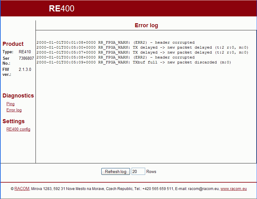
When the radio modem is in operation packet processing messages are generated:
Overwiev of reports RR_FPGA_WARN:
TX busy -> new packet discarded (for IP only)
A new request for transmission is discarded because transmission is currently taking place.TXbuf full – timeout!
A TX_STOP signal didn’t arrive from FPGA.Input buffer store timeout. Old packet discarded.
The packet has been waiting for such a long time in the input buffer (4min) that it is discarded.Fragment – sequence error
The serial number of the fragment does not correspond to that expected.Fragment – total number error
Information about the total number of fragments does not correspond to the previous fragment.Fragment – source address error
The received fragment is from another source address (serial number of radio modem) than the previous fragment.Fragment – receive timeout
The next fragment (does not apply to the first one) did not arrive within the timeout period (timeout is given by the transmission time of a single fragment in RFC).Fragmented packet being transmitted -> new packet delayed
Transmission of a packet has been held up (the packet is stored in the input buffer) owing to transmission or receipt of a fragmented packet. During receipt this doesn’t apply to the first fragment (it is not yet known that it is a fragment).Fragment – missing first fragment
A fragment not marked as the first has been received (and the first hasn’t yet been received).Compression inflate error
Packet decompression error.Compression deflate error
Packet compression error.Receive process interrupted
Received data is damaged because transmission occurred during receipt.(ERR2) – header corrupted
FPGA does not understand the packet header (another version of the protocol in the air or interference).(CRC16) – header corrupted
CRC16 didn’t appear in the header of the received packet.(CRC32) – data corrupted
CRC32 didn’t appear in the data of the received packet.
The following messages only for Number of repeaters > 0 :
Returned packet -> discarded (for NoR>0)
The same packet that was sent arrived back during the timeout period.Same packet -> discarded (for NoR>0)
The same packet, but with a different source address, was repeatedly received during the timeout period.TX delayed -> new packet delayed (for NoR>0)
Packet transmission has been held up owing to activation of delays related to the repeater.TXbuf full -> new packet discarded (for NoR>0)
A packet for sending is already waiting in the input buffer. A new one is therefore discarded.
There is fully functional firmware in the radio modem from production. When a firmware upgrade is required, take the following steps (example for fw version 2.1.7.0). It is necessary to use user account with administrator privileges. Remember switch off the firewall in the PC.
Install application trloader to your PC
Download installation package, e.g.:
2.1.7.0/trloader-win-gui-0.1.3.0.exehere:www.racom.eu/Download/Archive/ECONOMY radio modems/
start
trloader-win-gui-0.1.3.0.exeFolder
c:\Racom\Trloaderwill be created with respective files there.Download respective firmware, e.g.
2.1.7.0/tr1-2.1.7.0.rpgc:\Racom\Trloaderfolder, the latest version may be downloaded here:www.racom.eu/Download/Archive/ECONOMY radio modems/
Note – do both downloadings from the same folder, e.g.:
2.1.7.0/.Start
fwtrloader.exeinc:\Racom\Trloaderfolder.Use
Settings/Select Firmware packagein order to select a package of respective firmware (e.g.tr1-2.1.7.0.rpg). The application creates folderc:\Racom\Trloader\fw_pkgwith the respective files.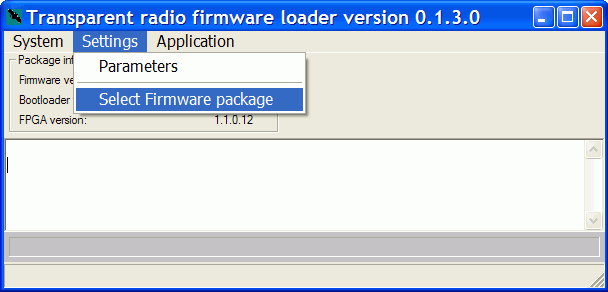
Firmware download
Put in PC suitable statical IP address, e.g. 192.168.1.233/24,
connect RE via Ethernet and start it in the bootloader mode
(start with
pressed RST button, STATUS LED is flashing yellow quickly, address used
192.168.1.1).
Continue with fwtrloader.exe. This utility is
accessible also from windows menu Start:
Start, Programs, Racom, TrLoader, Firmware Transparent loader
Select
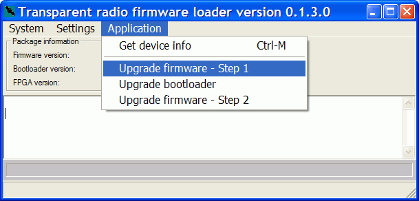
Application/Upgrade firmware-Step1(download the first part of firmware, takes approx. 45 sec, STATUS LED is flashing yellow slowly, address 192.168.1.1)
Select
Application/Upgrade bootloader(download the new bootloader module, approx. 40 sec, STATUS LED is flashing yellow slowly, address 192.168.1.1)
This step can be omitted, if the bootloader in RE is not older then version mentioned in the file:
c:\Racom\Trloader\fw_pkg\tr1-2.1.7.0\bootloader\COMPAT
The check is accomplished automatically at
 Upgrade
          firmware-Step2
. If the return to the stepUpgrade bootloaderis necessary then the report appears:
Select
Application/Upgrade firmware-Step2(download the second part of firmware, takes approx. 150 sec, STATUS LED is flashing green slowly, address 192.168.1.2)
Select
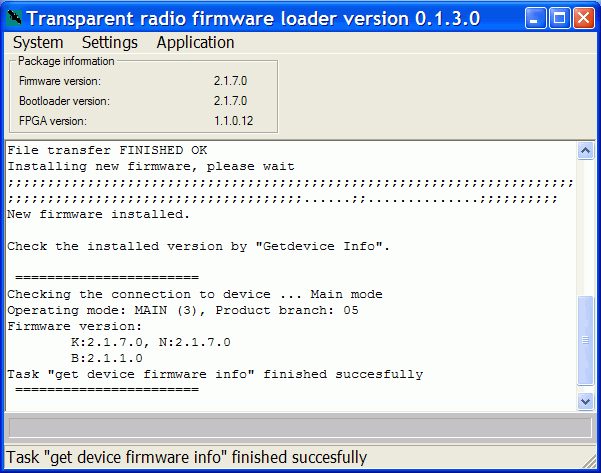
Application/Get device inforeturns the actual fw version from the radio modem. It is also possible to set the customer’s IP address (
Settings/Parameters/altIP) instead of the original 192.168.1.2 for reading the fw version from other radio modem. The loader uses the addresses in order 192.168.1.1, 192.168.1.2 andaltIP.When downloading more consecutive RE, then clear the arp records in PC. In Windows take the following steps:
Start / Run / cmd
arp -a               ...reads arp records
arp -d               ...clears all arp records
arp -d 192.168.1.2   ...clears arp records for written address
