Before you install the device to a mast tube, verify visually that the view in the direction of the remote unit is unobstructed.
Line of sight considerations:
Free Fresnel zones. Signal needs space wider than the diameter of the antenna.
Trees at the lower end of the Fresnel zone. They will be taller in a few years.
Possible building development.
Objects in the close proximity of the antenna such as edges of other antennas, their mounting racks, edges of the roof.
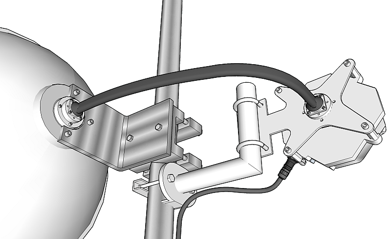
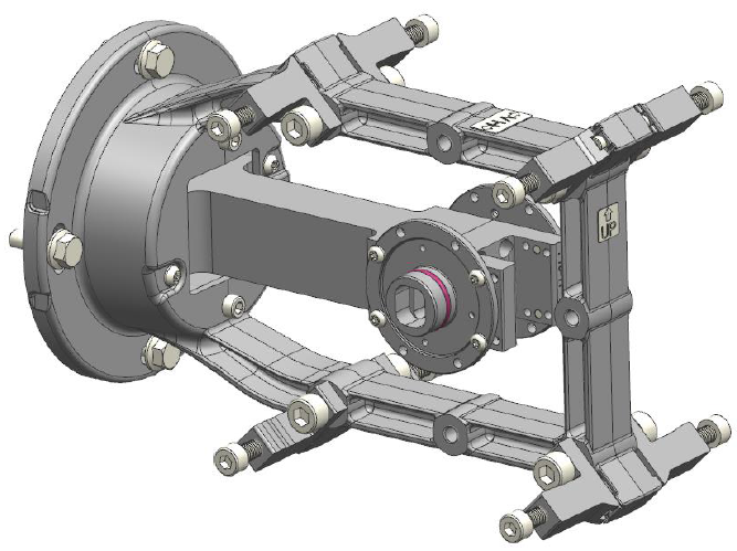
Antenna mounting depends on the antenna vendor, antenna type and the size of the chosen antenna. The result of any antenna installation is that it is fixed to the mast, pointing to the right direction and its waveguide and fixing screws are ready for mounting RAy unit to it.
 |
 |
| Left-side mounting – horizontal RX polarization | Right-side mounting – horizontal RX polarization |
Common for all antennas is a holder which ensures:
fixing of the antenna to the mast
flexibility in two planes (necessary for antenna adjustment to the proper direction).
Each holder allows at least 2 methods of mounting antenna on the mast tube:
right-side mounting
left-side mounting
Following sections describe in detail installation of antennas, mounting kits and/or flexible waveguides, so the antenna is ready for mounting RAy unit to it. Choose below a chapter relevant for your antenna supplier and installation manual according antenna type and size.
| Note | |
|---|---|
Each antenna allows RAy unit to be mounted on it with horizontal or vertical RX polarization. This is discussed in detail in Section 4.3, “RAy unit mounting”. |
Mounting instructions for each LEAX-RAy antenna are shipped with each antenna. Identical mounting instructions are available within RACOM RAy download section, on our website. See list below:
Installation of 30cm antennas – ANT-LEAX-300-inst.pdf
Installation of 60cm antennas – ANT-LEAX-600-inst.pdf
Installation of 90cm antennas – ANT-LEAX-900-inst.pdf
optionally with standard strut – ANT-LEAX-strut-std-inst.pdf
Installation of 120cm antennas – ANT-LEAX-1200-inst.pdf (includes standard strut)
optionally with extra strut – ANT-LEAX-strut-extra-inst.pdf
Installation of RAy interface for LEAX-RAy antennas – ANT-LEAX-RAy-inst.pdf
(same for all sizes). The RAy interface is part of each LEAX-RAy delivery (one interface set per antenna). It needs to be mounted to each antenna according to the instruction manual before mounting the RAy unit. Four pcs M8x30 (Allen) screws to mount the RAy unit to the antenna are also part of the antenna delivery.
Item ANT-LEAX-STRUT-90 (for 90 cm antennas) respectively ANT-LEAX-STRUT-120 (for 120 cm antennas) allows to increase operational wind speed up to 65 m/s (instead of 50 m/s respectively 55 m/s). Also allows to use tower pipe Ø50-120 mm (instead standard Ø90-120 mm).
Ensure the pin lubrication is completed during assembly.
Mounting instructions for Jirous antennas are available on the manufacturer’s website http://en.jirous.com. Mounting is also described in detail on RACOM RAy download section:
Installation of Jirous antennas ANT-JRM-inst.pdf
4 pcs M8x30 (Allen) screws to mount the RAY unit to the antenna are part of the antenna delivery.
Item ANT-JRMB-1200-STRUT-F or ANT-JRMB-1200-STRUT-A (optional wind bracing sets, both for 120 cm antennas) allows to increase operational wind speed for extreme sites.
Ensure the pin lubrication is completed during assembly.
Antenna which do not have a direct interface to RAy needs also a proper antenna mounting kit or a flexible waveguide with a mounting kit for it. Such interface has to be installed prior to RAy unit installation to the antenna.
Antenna mounting kit can be ordered as an accessory part (one per antenna). It has to be chosen according to selected band and antenna vendor – contact your local supplier or RACOM to check currently available types. Any other antenna can be connected to the RAy by standard flexible waveguide. RACOM offers mounting kits (RAy holders) for different flexible waveguides (see Accessories and the picture Flexible waveguide).
Standard mechanical tools are enough to install each of those accessories.
Items “SET-RAYxx-ARK” (where xx is the band) fits all traditionally produced Arkivator antennas (from company Arkivator, acquired by LEAX Group) as well as today produced Arkivator antennas from company LEAX Arkivator Telecom sold without RAy interface.
NOTE:
All LEAX-RAy antennas listed in the RACOM portfolio contain specific
RAy interface and thus no mounting kit is required.
Items “SET-RAYxx-ANW” (where xx is the band) fits most of Andrew antennas manufactured by CommScope with specific vendor’s interface unmounted. Suitable models of Andrew antennas are listed below. RAy2-10, RAy2-11 and RAy2-18 can use Single polarized antennas. RAy2-17 and RAy2-24 need Dual polarized antennas.
for 10 and 11 GHz bands use ANT-ANW-KIT-10/11 from RACOM and order the following single-polarized antenna types:
VHLP2-11W/A 60 cm
VHLP3-11W/A 100 cm
for 17 GHz band use ANT-ANW-KIT-17/18 and order the following dual-polarized antenna types:
VHLPX1-18W/A 30 cm
VHLPX2-18W/A 60 cm
VHLPX3-18W/A 100 cm
NOTE:
The antennas labelled for 17.700 – 19.700 GHz band are also OK for 17.100 – 17.300 GHz band (confirmed by CommScope).
for 18 GHz band use ANT-ANW-KIT-17/18 and order the following single-polarized antenna types:
VHLP1-18W/A 30 cm
VHLP2-18W/A 60 cm
VHLP3-18W/A 100 cm
for 24GHz band use ANT-ANW-KIT-24 and order the following dual-polarized antenna types:
VHLPX1-26W/A 30 cm
VHLPX2-26W/A 60 cm
VHLPX3-26W/A 100 cm
NOTE:
The antennas labelled for 24.250 – 26.500 GHz band are OK for 24.000 – 24.250 GHz band (confirmed by CommScope).
NOTE:
Ordering codes with “-W/A” at the end means one of suitable types of
waveguide (vendor’s interface), must be unmounted before installation of RAy antenna
mounting kit. Ordering codes with “-GDC” at the end means no vendor’s interface, so
nothing needs to be unmounted in such a case.
If there is a requirement to connect different type of antenna (for example some newer antenna type), it is possible to modify the existing adapter to meet new requirements.
Flexible waveguide mounting kit can be ordered as an accessory part.
Flexible waveguides themselves are not offered by RACOM – please consult your antenna supplier.
Ensure the pin lubrication is completed during assembly.
Antenna extensions for dual polarization are available for bands 10, 11 and 18 GHz using OMT extenders on LEAX-RAy antennas – see overview. It enables to double the link capacity by mounting two RAy units on a single antenna with each unit operating in a different polarization. OMT extenders need to be quoted as separated items (one extender per antenna).
Each RAy unit mounted on an OMT extender provides the same technical parameters and same level of service as a unit mounted directly to the antenna (without OMT between) except when both RAys are transmitting and receiving data on identical channels (on identical frequencies). In this situation the solution provided using an OMT extender generates slightly poorer SNR and thus higher modulations may become difficult. This may influence maximum distance and/or capacity of the link). See Application Notes for more details.
OMT extender allows the customer to install one RAy unit only; in such a case a special kit (item LEAX-OMT-LID, 6-8 weeks lead time) has to be ordered. This kit works as a ‘blind flange’ instead of the 2nd RAy unit. It protects the OMT against moisture. For details contact RACOM’s Technical Support (support@racom.eu).
OMT = Orthomode transducer
Mounting instructions for LEAX-RAy dual polarization extender (OMT) are part of each delivery (inside the shipped box with every OMT). Identical mounting instructions are available on RACOM RAy download section in separate document ANT-LEAX-dual-RAy-inst.pdf.
Ensure the pin lubrication is completed during assembly for each RAy unit installed.
| Note | |
|---|---|
Active network components (routers) need to be installed and configured on both ends of the link for a dual-polarized antenna with 2x RAy. The routers divide the data stream to both RAy links and then merge it again after transmission. Please consult RACOM Technical Support before quoting this option. See also the application note Dual-RAy & OMT. |
RAy unit can be attached to several different models of antennas from several vendors. Installation of RAy unit on to LEAX-RAy or Jirous antennas or to any other antenna through proper RAy mounting kit (eventually with flexible waveguide) is very simple and it is identical for all antennas and mounting kits. Installation starts with the lubrication of antenna pivot, followed by fixing the RAy unit in a proper position to the antenna and finished by unit grounding to the mast – as described in following sections.
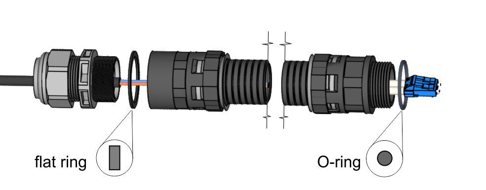
Before fitting the RAy bushing to the antenna pivot ensure the “O” ring (part No. 1) is in the correct position. It is also essential to prevent moisture getting in between these two parts. This moisture could cause oxidation which would complicate disassembly of this mechanical coupling in the future. For this reason we need to treat these surfaces with the grease enclosed in the box. If you use a different grease for lubrication then it should be a Teflon or a silicone grease.
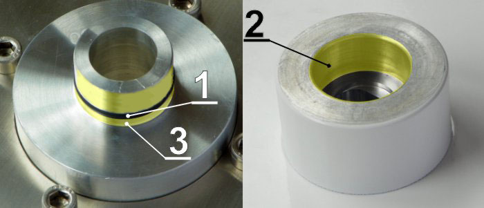
Lubricate both the internal area of the bushing on the RAy unit (2) and the “O” ring (1) with a thin even layer that allows the pin to slide easily into the bushing without damaging the “O” ring. The layer has to be really thin and even to ensure no grease is pushed in to the waveguide. A little bit more grease may only be applied in the area (3) beyond the “O” ring on the antenna pin to optimally fill the small gap (max. 0.1 mm) between the pin and the bushing to prevent leakage of moisture and water into the unit. Installation should be carried out according to the antenna installation instructions.
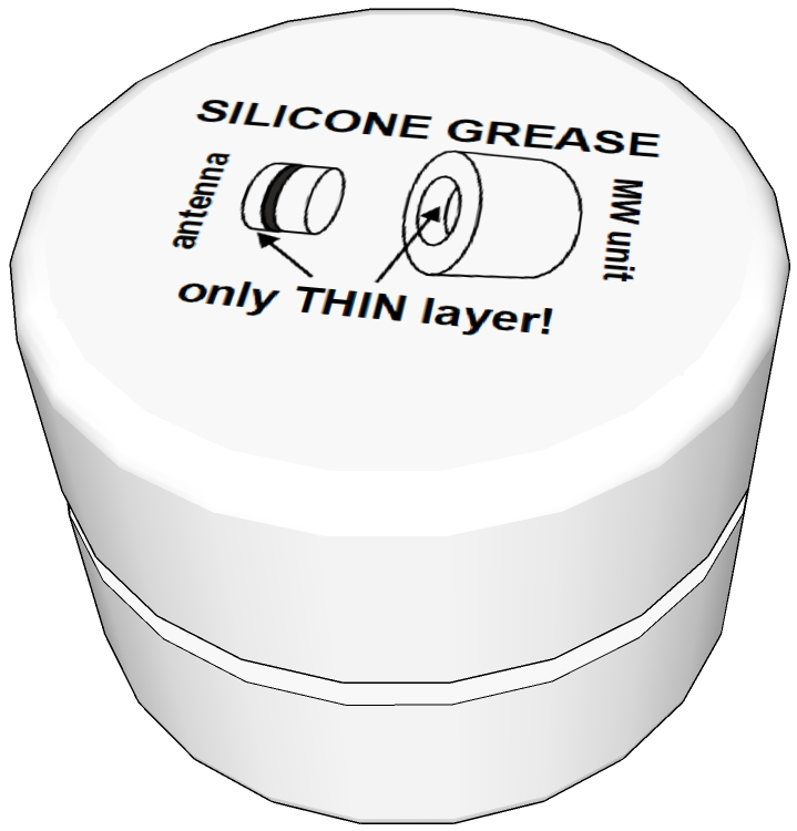
A capsule of grease is supplied with each RAy unit.
| Important | |
|---|---|
Lubrication is a very important assembly step for every RAy unit. Failure to lubricate the unit can lead to operational and assembly complications. |
Each antenna allows RAy unit to be mounted on it with different polarization:
horizontal RX polarization
vertical RX polarization
In all cases mount the unit with the connectors facing downwards at an angle.
| Note | |
|---|---|
RAy-17 and RAy-24 links need one unit to be installed with vertical polarization and the other unit with horizontal polarization because these models use cross polarization. RAy-10, RAy-11 & RAy-18 require the same polarization at both ends of the link to be used. |
RAy unit is fixed to the antenna by 4 pcs M8x30 (Allen) screws, which are part of the delivery of each antenna or each mounting kit. Those should be partially unscrewed so that the unit can be slid on to them. Then check whether the “O” ring is correctly fitted on the antenna pin, and make sure it is not damaged and has been lubricated with grease – see Section 4.3.1, “Lubrication of the antenna pivot” above.
Then remove the protective plastic cover from the central pin of the antenna and fit the unit flange (located in the center of flat part of RAy unit, across the holder) to it carefully not to damage the “O” ring. Once the RAy unit is plugged to the antenna pin, turn RAy clockwise so its screw-holders fit the right position for all 4 screws. Carefully ensure the correct polarization of the unit – see Section 4.3.2, “RAy unit mounting to the antenna” and secure the RAy unit in place with all four bolts. Finally, gently tighten the bolts with a No. 6 Allen key.
| Important | |
|---|---|
Gently tightening all 4 screws is enough. Do not over-tighten any screw, it may damage the protective color surface of the aluminum unit (enforcing corrosion processes) and in the case of an extreme force also deformations of the RAy aluminum cover may happen. Later de-installation of the unit then becomes difficult. Please ensure that all 4 screws are tightened equally during tightening and the gap between RAy screw-holders and spacers on all 4 sides of the RAy unit is approximately identical. Too strong tightening of one or 2 screws on one side of RAy unit may lead to the deformation of the sensitive zone of the waveguide between the antenna and the unit, resulting in weaker radio parameters. Even a small residual gap between RAy unit and the antenna is OK, because important is a good connection of waveguide – it is good enough even with screws gently tightened. NOTE: on older LEAX-RAy antennas (shipped during the year 2017) the residual gap under each screw-holder on RAy and antenna body may be up to 1 mm. |
RAy unit has to be properly grounded, otherwise it can not be guaranteed its function and it can be even damaged. Grounding connection through antenna and its holder is not enough (due to color surface, oxidation etc.), thus a separated grounding is required to ensure the perfect galvanic connection.
| Important | |
|---|---|
The RAy unit has to be grounded before connecting to the power supply and/or to the user network. |
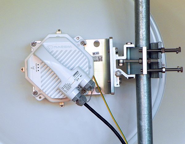
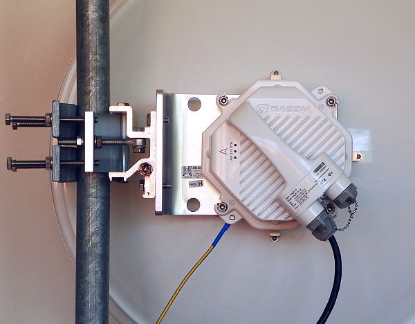
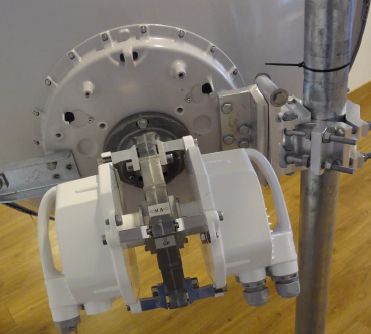
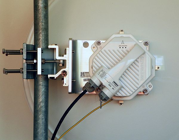
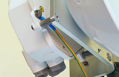
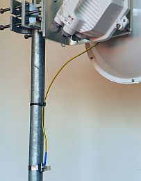
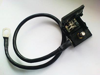
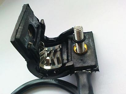
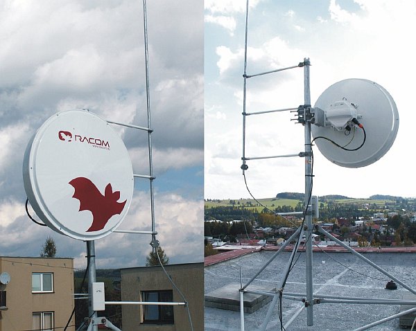
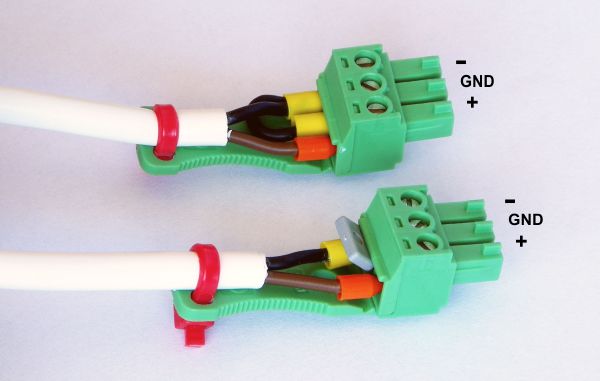
Typically the unit is grounded to the antenna mast, which has to be properly grounded (according Fig. 4.21, “Grounding installation 1” and Fig. 4.22, “Grounding installation 2”, where unit grounding to the antenna mast is marked by yellow-green cable).
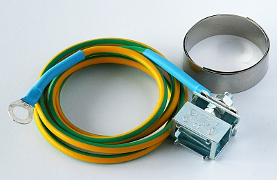
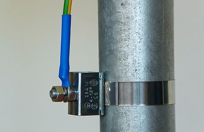
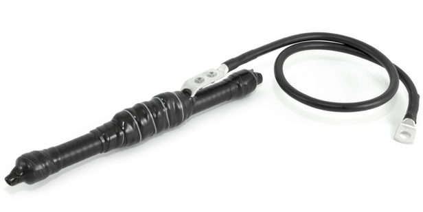
The RAy2 unit is grounded to the flange at the fixing screws using an M8 screw. An insulated copper cable with a minimum cross-section of 6 mm2 terminated with a terminal lug is used as a protective conductor. The conductor should have a green/yellow plastic cover along its whole length. The RAy grounding kit can be ordered as an accessory (see Chapter 2. Accessories) containing a grounding terminal ZSA16, 40 cm grounding strip 15 mm wide, and 100 cm of cable with grounding lugs. For instructions on installing terminals see the datasheet RAy grounding kit. The antenna must be installed by a qualified person.
Properly installed unit grounding kit (from RACOM accessory) is documented on photos below.
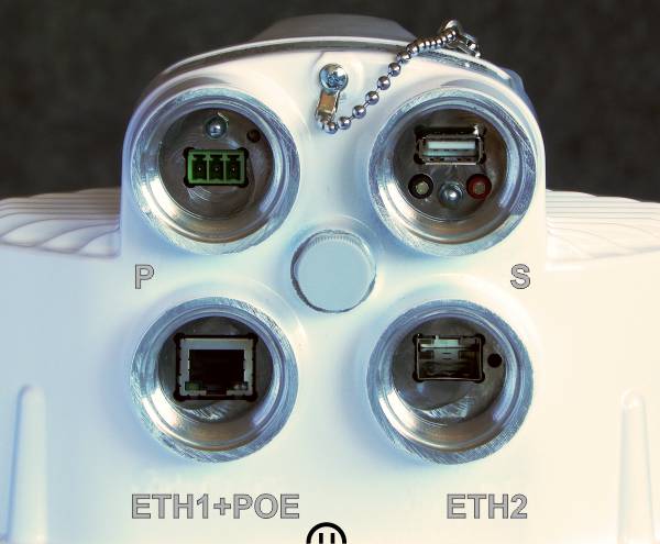
The unit is equipped with 4 standard connectors described in detail (including connectors’ pin-outs) in Section 1.3, “Ethernet + power interfaces” . Use only standard counterparts to these connectors.
A set of standard bushing and plugs is delivered with each RAy unit as an accessory ACS-RAy2. The rubber sealing for each bushing is delivered with three different internal diameters to fit different cable diameters. The rubber is diagonally cut to enable sealing of cables with preinstalled connectors.
If the lengthening of the bushing is needed use the long bushing delivered within standard accessory kit ACS-RAy2 or purchased separately as an option SET-BUSH65 (providing 65 mm long inner space for connector) or the long extension OTH-BUSH-EXT500 (adds up to 50 cm).
| Important | |
|---|---|
Before connecting the RAy unit to the power supply and/or to the user network it must be grounded according to Section 4.3.3, “RAy unit grounding” All cables have to be secured by appropriate bushings which must be fitted with relevant O-rings and carefully tightened in, according the instructions below. Remaining connector slots on RAy unit has to be secured by plugs (including the original plugs in the flanges). Those must be fitted with O-rings and carefully tightened as well. Otherwise, the unit is not protected against moisture intake through connectors and can not guarantee unit functionality. |
Assembly variants:
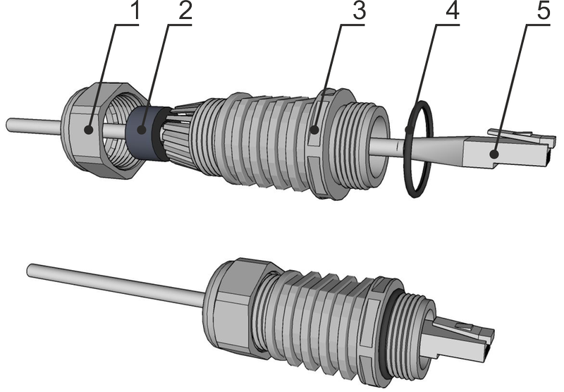
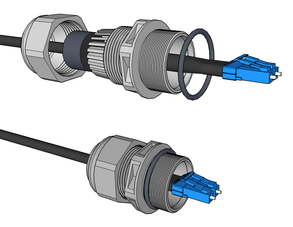
Fig. 4.17: Bushing assembly for metallic Ethernet with long ETH connector (or for non-OFA fibre optic cable)
| Important | |
|---|---|
At the outer end of the long lengthening there is necessary to use a flat ring supplied as part of the OTH-BUSH-EXT500. On other places O-rings are used. See Figure above: |
Assembly procedure:
Put on the cable: the nut No.1, rubber sealing No.2, bushing No.3 and O-ring No.4.
(If you use extension ring No. 6 with O-ring No.7 put those on the cable as well.)Attach the appropriate connector No.5 to the cable.
Plug the connector No.5 into the RAy2 unit.
(If you use extension ring No. 6 with O-ring No.7, lubricate its thread with grease and screw those into the RAy2 unit.)Screw the bushing No.3 with the sealing O-ring into the RAy2 unit.
Move the rubber sealing (2) along the cable to fit in the bushing. Screw the nut (1) on bushing (3).
(If you use extension ring No. 6 with O-ring No.7 lubricate its thread with grease.)
Disassembly procedure:
Release the nut No.1
Remove the rubber sealing No.2
Unscrew the bushing No.3 with O-ring No.4 (and extension No.6 with O-ring No.7).
Remove the connector.
| Warning | |
|---|---|
It is absolutely critical first to completely release and disassemble the nut No.1 and remove the rubber No.2. Failure to do so could cause the damage of Ethernet cable or fibre optic wire by cable rotation. Even connectors inside the RAy unit can be damaged. Should the rubber sealing No.2 become fastened to the cable and/or to the plastic bushings, the rubber sealing must be detached from the cable by a brute force. We suggest you use a flat screw driver to release the rubber sealing No.2. It is always better to optionally damage the bushing rather than damage a cable or components inside the RAy unit. |
| Important | |
|---|---|
|
The proper grounding together with surge protection components should be installed on site to increase the resiliency of the whole installation against natural overvoltage situations (stimulated by storms, lightning and other atmospheric issues). Such a system has to respect local standards for grounding and electromagnetic protection, otherwise the risk of damage of the unit and/or connected IT infrastructure gets much higher. We also recommend to consult each site situation with local experts to ensure the installed grounding is enough for the actual site conditions and that the overvoltage protection of sensitive components or infrastructures is reasonably effective against typical situations on site.
The rule is that every metallic component of wireless infrastructure located outside the building (in LPZ0) should be properly grounded and protected against overvoltage, especially:
grounded RAy unit itself (as described in Section 4.3.3, “RAy unit grounding” )
grounded all shields from all metallic Ethernet cables
grounded all DC cables (shields or one wire)
overvoltage protection is applied on all metallic Ethernet cables at the point of entrance to the building
overvoltage protection is applied on DC cable at the point of entrance to the building
All types of cables should be grounded and longer cables should be grounded in several places (outside the building every few meters). Overvoltage protective devices are available for all types of cables and usage. Accessories offered by RACOM for those purposes are listed in Grounding section of RAy web site.
| Important | |
|---|---|
The unit and mast must be properly grounded before the power supply and/or the user network are connected to RAy unit. Warranty does not apply for units destroyed by surges or over-voltage (see RACOM warranty conditions at Section 10.8, “Warranty” ). |
| Note | |
|---|---|
Some PoE power sources, PoE injectors and DC power supplies have overvoltage / surge protection built in. Please consult the datasheets of those versus the local standards and site requirements. On sensitive sites additional overvoltage protection should / could be applied between different zones (or rooms) even within one building (for example between network center and datacenter). LPZ acronym means Lightning Protection Zone. |
The example and rules below are designed in accordance with regulation EN 62305.
Where possible the antenna should be located in an LPZ 0B protection zone with the use of a local or artificial air termination device for protection against direct lightning strikes.
When meeting conditions for ensuring electrical insulation (distance from the lightning conductor) in accordance with article 6.3 of this standard, it is not recommended to ground the load-bearing structure and antenna to the external air termination network. Grounding should be attached to the protective system of the internal LV (Low Voltage) wiring or grounded internal structures using a CYA 6 mm2 bonding conductor , see Fig. 4.21 Grounding installation 1.
If it is not possible to set up conditions of electrical insulation in accordance with article 6.3 of this standard, we recommend connecting the load-bearing structure at roof level to the external air termination network via an 8mm diameter FeZn conductor and shielding the data cable before entry to the building with a grounding kit and CYA 6 mm2 conductor to the bonding bus, and if not already set up then also to the external air termination network, see Fig. 4.22 Grounding installation 2.
If there is not an external LPS on the building we recommend routing lightning current through an 8mm FeZn conductor to a common grounding system, or to a separate grounding electrode with a ground resistance up to 10 Ω.
For limiting the overvoltage transferred over the data cable and into the building we recommend fitting surge protection at the interface between zones LPZ 0 and LPZ 1 connected via a CYA 4 mm2 conductor to the same grounding point as the antenna or the antenna mast.
We recommend protecting the PoE power supply from overvoltage on the LV side with suitable class D surge protection.
Racom supplies surge protection for installation on Ethernet cables entering buildings. For more details see Surge protection.
Additional safety recommendations
Only qualified personnel with authorisation to work at heights are entitled to install antennas on masts, roofs and walls of buildings.
Do not install the antenna in the vicinity of electrical wiring. The antenna and bracket should not come into contact with electrical wiring at any time.
The antenna and cables are electrical conductors. During installation electrostatic charges may build up which may lead to injury. During installation or repair work to parts of the antenna lead, bare metal parts must be temporarily grounded.
The antenna and antenna cable must be grounded at all times.
Do not mount the antenna in windy or rainy conditions or during a storm, or if the area is covered with snow or ice.
Do not touch the antenna, antenna brackets or conductors during a storm.
Note – It is always better not to install the microwave unit directly under the lightning conductor holders. There is lower probability of unit being polluted by birds.
It is necessary to install the Ethernet lead so that there is no excessive mechanical stress applied on the connector bushing:
RAy microwave unit can be powered by active PoE, passive PoE or by DC power source. All PoE are supplied through RJ45 Ethernet connector (in slot “ETH1+POE”), for DC power sourcing there is a dedicated DC connector (in slot “P”). Detailed description and technical parameters of both connectors can be found in Section 1.3, “Ethernet + power interfaces” . RAy unit doesn’t support a combination of DC + PoE power supplies in the same time.
RACOM is offering all kinds of power supplies, all guaranteed for compatibility with RAy unit and tested for long-term stability – they are listed in Powering section of RAy web site.
PoE power sourcing compatible with RAy unit:
Active PoE plus (called also Standard PoE+) power supply compatible with IEEE 802.3at, sourced by AC or DC power. The standard IEEE 802.3at defines negotiation method, wires to be used, operating voltage (36-56V), maximum supported current, overcurrent protection and other parameters. Any power supply compatible with IEEE 802.3at standard can be used.
Passive PoE power supply (called sometime PoE injector), is an equipment pushing to the pins of Ethernet connector DC power with a polarity and voltage compatible with IEEE 802.3at standard. Thus, supported voltage, distances, grounding and internal RJ45 pins wiring are identical with Standard PoE+ (mentioned above). Typically, the current is sourced from a DC power with adequate parameters (voltage 40-60V, max current at least 1A). The only additional requirement is that non-grounded wire of DC power circuit in to PoE injector has the be secured by a fuse disconnecting the power circuit in the case of over current (similar like for DC power source connected directly to the RAy unit by a DC connector).
![[Note]](/images/radost/images/icons/note.png)
Note Quality CAT7 Eth cable (i.e. shielded one) with UV protection is recommended for outside use.
Quality connectors (like CON-RJ45-CAT7) are recommend to be used on both ends of Ethernet cable to ensure long-term reliability of the connection. Such connectors have better resistance against oxidation and also against scorching contacts due to spikes during power-on and power-off the unit by plug / unplug Ethernet cable. Anyhow standard Eth cable with standard Eth connectors should work as well.
Overvoltage protection unit is recommended to be applied between RAy unit and PoE power supply – for details see Section 4.5, “Grounding” (easily visible on Fig. 4.21, “Grounding installation 1”).
DC power sourcing compatible with RAy unit:
Any kind of DC power source can be used to power the unit through the DC male connector (supplied with each RAy unit) plugged in to “P” 3-pin DC connector. The DC power circuit must be fitted with a fuse to protect against short circuiting (or power supply has to have such a fuse built-in). Power supply has to be able to provide enough power both for the RAy unit plus to cover the energy loss on the DC cable.
RAy internal DC power circuits ensure galvanic separation. If the galvanic separated power source is used and the DC power line needs to be grounded (either positive or negative wire), the middle pin of the 3-port DC connector can be used to make a connection between ground and the respective power wire, see Grounding options (d), (e). If grounding is required it should only be made in one of the following ways: on the DC power source side or using ground pit on the 3-port DC connector plugged into the unit.
The next figure shows all available grounding options. We recommend the use of a galvanic separated power source and no additional DC grounding – see Fig. 4.28, “Grounding options” version c).
Connect a power supply to the installed RAy unit. Connect the device to be used for configuration via WiFi or ethernet cable. Access the configuration menu using browser or Alignment tool.
This is particularly true for installation of links working in free bands, where the user has no secured frequency.
Analyse the level of noise in the individual channels using the spectrum analyzer under Tools/Live data/Frequency spectrum analyzer. If necessary adjust the choice of working channel on the basis of the results.
While doing so respect the rule that in one location all units emit a signal in the Upper part of the range and receive it in the Lower part of the range, or the other way round. A transmitter must not be installed in the part of the spectrum where other units function as receivers.
For first antenna alignment, use a narrow channel, low modulation and high power where possible.
ATPC and ACM functions should be switched off (prevents Tx power fluctuations during alignment).
Where possible adjust both ends of link simultaneously to speed up the process.
Alternate adjustments at both ends of link in small increments both horizontally and vertically to establish position with strongest signal whilst looking for maximum main signal (see paragraph on main & side lobes).
RSS measurement chapter provides overview for available methods to measure RSS.
RSS measurement
To align antennas accurately connect a PC, tablet or mobile and use the diagnostic and measurement capabilities built in to the RAy unit. There are 4 tools available to support measurement of the 2 basic parameters for optimum antenna alignment: RSS (Radio Signal Strength) and SNR (Signal to Noise Ratio):
Voltmeter – indicates local RSS
RAy Tools smartphone application – indicates RSS, SNR – Local & Peer
Antenna Alignment Tool web page – indicates RSS, SNR – Local & Peer
Bar graph on Live Data page inside web manag. – indicates RSS, SNR, BER – Local & Peer
Before antenna alignment starts it is recommended to find out RSS and SNR values from the link design for the installed link or calculate these values yourself. There are 4 methods available with increasing levels of accuracy:
Module Calculation inside RAy Tools smartphone application
Link calculation on RACOM website
Use Link calculation chapter in Application notes
Precise link calculation using dedicated tools (e.g. Pathloss)
| Voltmeter |
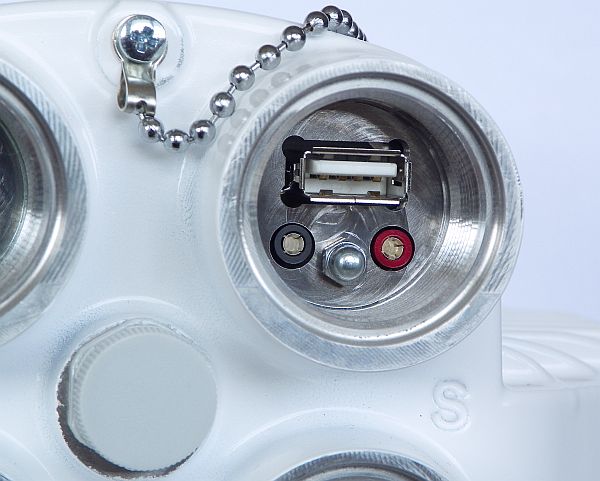  | |
| RAy units support traditional antenna alignment using a voltmeter measurement
representing RSS in dBm (only for a local unit). Connect a voltmeter with the range
2V DC via connectors to the operational unit and adjust antennas to the lowest
indicated voltage. Voltage is calibrated according to signal strength.
E.g.: RSS -65 dBm corresponds to voltage 0.65 V, RSS -80 dBm corresponds to voltage 0.80 V etc. | ||
| RAy Tools – smartphone application |
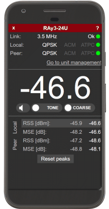 | |
|
RAy Tools is an application described in detail in Chapter 7. RAy Tools app for Mobile devices. Module Alignment displays RSS and SNR for both local and peer RAy unit. All key functionality in this module performs an identical function to Antenna Alignment Tool described in Section 5.6.2 Live data. More about RAy Tools in Chapter 7. RAy Tools app for Mobile devices. | ||
| Antenna Alignment Tool – html page within unit management |
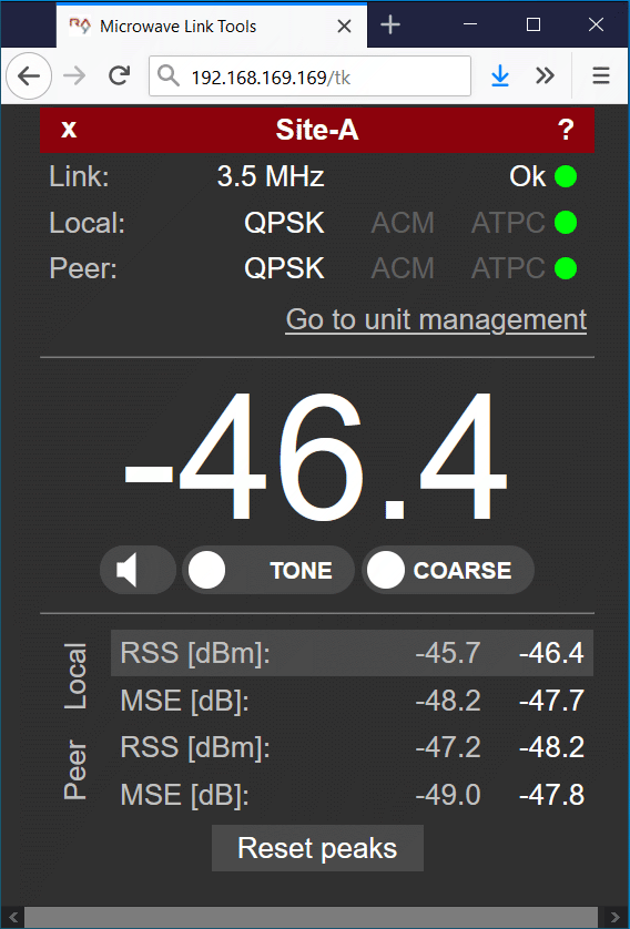 | |
|
Antenna Alignment Tool is optimized for devices with smaller displays. All values are refreshed ten times per second to enable smooth operation. The Antenna Alignment Tool is described in Section 5.6.2 Live data. The Tool is available on http://<ip>/tk, (e.g. http://192.168.169.169/tk for standard Ethernet ports, alternatively on http://172.17.17.17/tk in the case of connection through USB/WiFi or USB/Eth). The Tool is accessible without any username or password. | ||
| Bar graph in web management |
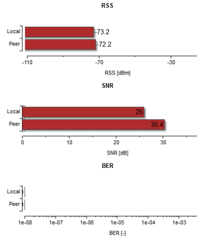 | |
|
Within user management Tools / Live data / Bar indicators shows bar graphs of RSS, SNR and BER (Bit Error Rate) values for local and peer units. Values are refreshed every second or manually. See Section 5.6.2 Live data for detailed information. NOTE: The BER value should be close to zero after antenna alignment. | ||
Main and side lobes
Directional antennas have a specific angle within which radio waves can be transmitted or received (Angle of Tx/Rx).
The strongest signal is emitted in a forward direction; the main lobe is a graphical representation of its direction of travel and strength.
However signals are also emitted and received from unwanted directions through side lobes. In receiving antennas this is a highly significant factor contributing to the level of interference in a radio network (See Fig. 4.29 Antenna lobe diagram ).
Fig. 4.30 Signal strength graph provides an indication of comparative signal strength from different beams emitted from a directional antenna.
Placing the antennas to the correct antenna alignment is very important to ensure the strongest signal is received:
Examples
Both antennas should be oriented towards each other using the peaks of the radiation diagram. Adjust the antenna alternately in the horizontal and vertical axes and monitor the resulting signal strength. Use the calculation of the expected RSS with the precision of several dBm as guidance. Side lobes transmit a signal ca 20 dBm weaker, see the Microwave link Calculation .
The resulting RSS helps distinguish between the states A-A and C-C which appear similar. It also helps in situations where simple search for a maximum doesn’t work as shown in the illustration “incorrect adjustment”.
Real radiation diagrams are more complex, especially in that they run differently in horizontal and vertical axes. The basic steps for determining the main radiation lobe however stay valid. For example:
Basic parameters of the link are shown in the menu Status/Brief, its quality is characterized by RSS and SNR. Values on Status screens can be refreshed manually by pressing the Refresh button or in real time with a period of several seconds after activating the Start button. Press the Stop button to terminate the periodic refresh of values.
The RSS, SNR and BER values can also be viewed on the screen Tools/Live data/Bar indicators. After pressing the Start button, values will be refreshed with a period of one second.
After installation, it is good to reset the statistics using the Clear stats button in menu Status/Detailed. This allows easier diagnostics of the link’s reliability over time.
After both antennas have been aligned, setup operation parameters for the link. In the case of links operating in the free band, setup the parameters based on survey results from the tool Tools/Live data/Frequency analyser. In the case of links operating on a licensed band, setup the parameters based on the assigned license.
Bandwidth
Channel Selection (TX / RX channel)
Modulation (TX modulation) – ACM is recommended. When selecting fixed modulation it is necessary to account for the fade margin. If fixed modulation is setup close to a possible maximum, then a deterioration in RSS could endanger the link both for data transfer as well as service access.
Transmit power (TX power), or ATPC
Verify and record IP addresses
Define access channels – https / telnet / ssh / ssh with password
Check the users password settings.
Restart both units by interrupting their power supply and verify the status of the link. This verifies that all parameters have been stored correctly in the memory.
Select Tools/Maintenance/Backup/Settings (Local & Peer)/Full and save the configuration to backup file “cnf_backup.tgz”.
This completes the installation. Further configuration can be performed remotely.