The Radio part menu only applies to communication units (CU) where the radio hardware is an integral part of the unit. The most typical example of such a unit is the MR400 or MR25.
Sub-menus Radio Hardware and Radio Parameters deal with the configuration stored primarily within the radio part of the hardware. Still both of these configuration data structures are kept in the communication unit RAM and SRAM or FLASH memories the same way as the “normal” ones.
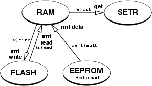
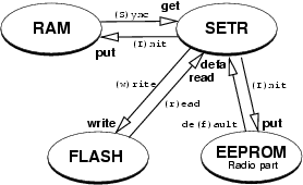
The relations between memory modules in Radio menu, compare fig. of memory in MORSE main menu.
Nevertheless it is important to be aware of the fact, that the actual working parameters are the ones stored in the radio part of the hardware. Due to this fact, some commands in the above mentioned menus behave differently from “normal” configuration menus. Utmost care must be taken when changing Radio part parameters in a remote unit, as the risk of irreparable communication breakdown is considerably high.
The specific commands behaviour is discussed in the appropriate paragraphs.
Similar to the unit HW parameters menu, this menu can be normally
used only for displaying the HW configuration of the radio part. The
actual working set of Radio HW parameters is stored in the radio part
memory and cannot be changed from this menu. These original parameters
are read by both DEFAULT commands (before and after the (e)dit
– see section Section 1.2, “CU Configuration Services”. These commands
can be performed at anytime, and must always be applied before any
change in Radio part has taken place.
| Caution | |
|---|---|
The copy of the radio part HW parameters in unit RAM is used e.g. as a basis for calculations of by SETR displayed frequencies. Thus a change of Radio part HW parameters can result in an incorrect display of these frequencies and possible the wrong setting and saving of it. |
MORSE main menu:

(H)W   (U)nit (R)adio
(N)odes  s(D)r   (B)c
(S)CC   R(F)C   (E)th
(A)rt   r(T)ab  (c)nf
(m)isc  NA(G)

(s)ervice      d(i)ag
(p)ath        (?)help

(o)ld cnf menu

(q)uit
type R Enter
Radio part:
(h)w data
(p)arameters
(c)alibration
(q)uit
>>
type he Enter Enter
Radio hardware:
product (t)ype:MR25R2
(s)erial:8543
(H)W ver:40  subver:1
flags:0000
S(W) ver:19
prod dat(e) d:28 (m):2 (y) 1970+:35
check date D:0 M:0 Y 1970+:30
MR(2)5R  MR(9)00
de(f)ault (r)ead (w)rite
(I)nit (S)ync
(q)uit
>>
This menu is meant for reading only.
| (t)yp | product (t)ype: MR25R — type of the radio part product type (G) GPRS - MG100 = modem with GPRS module instead of radio (2) MR25R2 - MR400, MR300, MR160 (M) MR25R - MR25 (9) MR900 - MR900 (N) NO RADIO - MC100, MCM302, MORCE, WALRUS | ||||||||||||||
| (s)er | (s)erial:8543 — Radio part serial should be equal to the serial typed on the production label | ||||||||||||||
| (H)W | (H)W ver:40 — version number of HW | ||||||||||||||
| flag | flags:0000 — the flags inform about some features of the radio part, e.g.:
| ||||||||||||||
| S(W) | S(W):19 — version number of SW | ||||||||||||||
| dat(e) | prod dat(e) — date of manufacture – day, month, year | ||||||||||||||
| check | check date — date of output check – day, month, year | ||||||||||||||
| MR(2) | MR(2)5R — frequency setting for MR25 and MR400 MR25R control: (c)h spacing:125*100Hz switching r(a)nge:32000*100Hz IF - (T)X:565000*100Hz (R)X:-450000*100Hz RX (2)nd:4550*100Hz base freq - T(X):4250000*100Hz RX(b):4250000*100Hz (q)uit >>
| ||||||||||||||
| MR(9) | MR(9)00 — frequency setting for MR900 MR900 control: base freq (0):8695250*100Hz base freq (1):8695250*100Hz (q)uit >>
|
Some of the Radio part parameters stored in its memory have to be accessible for changing by the main unit software (namely RX and TX frequencies, output power and status bits). These parameters are concentrated in the Radio parameters configuration structure and can be edited in the following menus.
The same way as in the Radio HW parameters menu, both DEFAULT
commands read all data from the Radio part memory. The most important
difference from the Radio HW menu is that anytime the data in the unit
RAM are changed (e.g. after (I)nit command), new values of
power level and synthesizer rates are calculated and written to the
Radio part memory. These calculations use some values from the Radio HW
parameters structure, so it is absolutely necessary to have correct
values in the Radio HW structure in the main unit RAM before making any
change to Radio parameters. If in any doubt it is strongly recommended
to enforce the de(f)ault command from the Rh
menu (see (R)adio (h)w data for more
details).
From MORSE main menu type Rpe Enter Enter:
Radio parameters:
(T)X:4264750*100Hz  (R)X:4264750*100Hz
Frequency off(s)et:NONE  :0
Power - (l)evel:7  mW:275
(c)heck period:0
(1)-tx  (2)-rx
de(f)ault (r)ead (w)rite
(I)nit (S)ync
(q)uit
>>
| (T) | (T)X:4264750 – transmitter operating frequency (in 100 Hz). Only these frequencies can be saved, which correspond to the frequency grid according to the parameter (c)h spacing (Rhe 2c menu). Check the right saving using (r)ead, (S)ync. Since 12/2008 is the frequency step indicated also in the production code. |
| (R) | (R)X:4264750 – receiver operating frequency (in 100 Hz) |
| (s) | Frequency off(s)et:NONE :0 – active at radiomodems having the frequeny step 6.25 kHz only, see (c)h spacing and production code. It increases the frequencies set by the parameters (T)X, (R)X by 6.25 kHz. |
| (l) | Power – (l)evel:7 mW:275 – transmitter power level is set by
hex number from 0 to F. The displayed value in mW is calculated
during the |
| (c) | (c)heck period:0 – for service purposes |
| (1),(2) | (1)-tx (2)-rx – alternative frequencies used by the mobile mode. More informations in the manual MORSE Guide 2 |
Allowed TX freqs: (*100Hz)
(0) :4264750  (8) :0
(1) :4265000  (9) :0
(2) :0  (A) :0
(3) :0  (B) :0
(4) :4265750  (C) :0
(5) :0  (D) :0
(6) :0  (E) :0
(7) :0  (F) :0
(q)uit
>>
The items (0),(1)…(F) represents the individual frequency channels. The parameters are filled in two ways:
Bases of mobile network – CU runs on the frequency written by the parameters (T)X, (R)X. The nonzero value of choosen parameters (0),(1)… label the frequency channels of Bases situated on common location.
Mobile – parameters (T)X, (R)X doesn’t need to be filled in. The frequencies written in choosen items (0),(1)… define the frequency channels where the Mobile can be retuned.
The Radio part provides the main unit with “raw” values from the A/D converters, which measure some important analogue signals (Received Signal Strength, internal temperature, supply and PLL voltages). To get the actual values in dBm, Volts, degrees etc., a set of computing constants is needed. A similar set of constants is needed to get the transmitted power value in mW for the configured power level number.
| Caution | |
|---|---|
All these constants are hardware related and are written to the unit flash memory during the production process. The Radio calibration menu allows for displaying and editing of all these constants. The default values provide a set of initial values to start the calibration process during production or maintenance. In normal situations, it is strongly recommended not to change anything in this menu. Especially any use of (w)rite commands can result in the need to send the affected unit to the manufacturers premises for re-calibration. |
From MORSE main menu type Rce
Enter Enter
Radio calibration:
RSS  - (a)c0:34496  (b)c1:97
t(e)mp - c0:0  (g)c1:300  (h)c2:0
AF v(o)lt c0:22
main pll - (T)X c0:111  (R)X c0:111
loc  pll - (t)x c0:111  r(x) c0:111
(U)cc volt c0:111  RSS (v)olt c0:20
power level constants
(0):0 (1):0 (2):0 (3):0 (4):0 (5):0 (6):0 (7):20000
(8):0 (9):0 (A):0 (B):25700 (C):0 (D):28399 (E):31700 (F):37000
de(f)ault (r)ead (w)rite
(I)nit (S)ync
(q)uit
>>
In the given example of power level constants it is
visible, that this modem ((H)W ver:30) is ready for using
Power levels 7,B,D,E,F. The modems (H)W version:40
can use all Power levels from 0 to
F.