RAy3 microwave units work as a wireless Ethernet point-to-point link in a full duplex setting with transfer speeds of up to 10 Gb/s. The link is formed by two RAy units, each equipped by its own parabolic antenna and accessories to be fully operational.
Supported are several license-free bands and several licensed bands, all in the identical aluminum box. Bandwidth can be configured from 3.5 up to 2× 112 MHz for standard bands (all models up to 24 GHz) and from 62.5 up to 2000 MHz for E-band (71-86 GHz). Adaptive modulation function can operate from QPSK to 4096QAM for standard bands. In the case of E-band modulations range from 2PSK up to 128QAM. The lowest modulation on each model could be on the fly (without data loss) strengthened for higher receiver sensitivity by extremely robust FEC – such modulation is marked as QPSK_S or 2PSK_BW/4_S (where ‘S’ means a strong FEC and ‘BW/4’ means a narrower channel used in E-band only). RAy3 microwave links operating in 17 and 24 GHz bands can also be operated as a Short Range Device (SRD).
RAy product line has been designed to have minimum possible number of hardware variants. Functionality of the unit is upgraded according to the “pay-as-you-grow” concept only by activating the relevant software feature keys and does not require any on-site hardware changes. For details see Section 1.7, “Ordering codes” and Section 5.6.1.2, “SW feature keys”.
HW models are determined only by frequency bands and in the case of licensed bands (i.e. 10, 11 and 18 GHz) also by sub-bands. Additionally in 10, 11, 18 and 80 GHz bands units forming a link differs in HW duplexer which ensures the proper frequency separation of transmitting and receiving channels. This is marked on each unit as Lower (L) or Upper (U) in Production code according the position of transmitting channel.
Units for 17 and 24 GHz does not have any HW difference between L and U units, because transmitting and receiving channels are freely defined by software and technically separated from each other by cross polarization.
Cross polarization means that one side of the link uses one polarization for transmission (e.g. horizontal) and the opposite polarization for receiving (e.g. vertical). The other side of the link is turned by 90°. Therefore it transmits and receives using opposite polarization with respect to the second unit. Practical result for users is that units for 17 and 24 GHz must be mounted with reverse polarity on both ends of the link.
| Note | |
|---|---|
All units for 17 or 24 GHz band are hardware identical. Default factory settings in the pair use different channels for L and U unit, so the link could be established by using default radio parameters. |
| Type | Band | Frequency range [GHz] | Sub-bands | Polarization | Note |
|---|---|---|---|---|---|
| RAy3-10 | 10 GHz | 10.12–10.68 | A (for CZ only), B (global) | Single polarization (Vertical or Horizontal) | Sub-band A is free-band in Czech Republic (CZ); Sub-band B is worldwide licensed band |
| RAy3-11 | 11 GHz | 10.70–11.70 | A (lower part), B (higher part) | Single polarization (Vertical
or Horizontal) | Worldwide licensed band |
| RAy3-17 | 17 GHz | 17.10–17.30 | – | Cross-polarization
(Vertical or Horizontal) | Free-band in several countries |
| RAy3-18 | 18 GHz | 17.70–19.70 | A (ETSI-lower part), B (ETSI-higher part), C (FCC) | Single polarization (Vertical
or Horizontal) | Worldwide licensed band |
| RAy3-24 | 24 GHz | 24.00–24.25 | – | Cross-polarization
(Vertical or Horizontal) | Free-band in EU, US, Canada and several other countries |
| RAy3-80 | 80 GHz (E-band) | 71–76 & 81–86 GHz | – | Single polarization (Vertical
or Horizontal) | Worldwide free-band or light-licensed band |
RAy is a typical Software Defined Radio product line, where all possible technical features are defined by the internal software. This internal software is distributed to users in a form of unit firmware (FW) developed by RACOM to optimally manage all hardware inside the unit.
The strategy is to have one common code-base to support all RAy3 models for all bands and sub-bands. It ensures that every advance in the FW development (i.e. every new feature or every bug-fix) is available on all relevant RAy3 units within the nearest FW release. Temporary exceptions (like a separate FW version for 10 GHz units) are sometimes necessary, due to the complexity of FW development.
Even the 80 GHz unit requires a different Linux kernel (due to the need of 10 Gb/s peripherals support) and thus the HW specific FW version exists, the code-base is still common across all HW models for all bands. Thus the user interface and most of its functions are identical across all models for all bands and sub-bands as much as technically possible (the only visible differences are due to different band / sub-band rules and band-specific radio HW).
RAy links support only the Ethernet type of traffic and they are transparent for IP and UDP packets. Practically all protocols pass through unmodified including MPLS, RSTP (BPDU frames) and many others, except following:
Management packets targeted for RAy units itself
Special packets for protocols explicitly mentioned in this manual, which are somehow processed by RAy units (like PTP)
Packets, which did not went through and were discarded due to capacity limitation and/or policy rules (e.g. PIRL, QoS, EGRES shaping …)
This chapter describes basic properties of each RAy unit, which are important for its mechanical installation: antenna waveguide, unit fixing (screws, etc.) and unit grounding (screw + cable). Other interfaces (for data, power and service purposes) are described in next chapters Ethernet + power interfaces and Service interfaces.
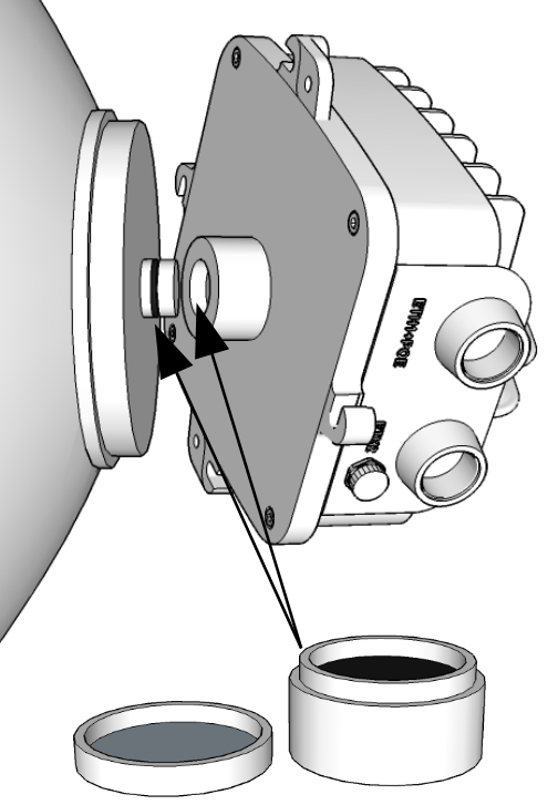
Antenna waveguide flange on RAy unit (located across the holder) ensures perfect microwave connection between the unit and the antenna. All RAy units are equipped with identicaly sized round flange (with the outer diameter 50 mm and the inner diameter 28 mm). The only visible mechanical difference between RAy models are the diameters of the round waveguide hole in the middle of the flange. Those diameters differs according frequency ranges and are following:
| 10-11 GHz | 19.00 mm |
| 17-18 GHz | 11.00 mm |
| 24 GHz | 8.00 mm |
| 70-80 GHz | 3.18 mm |
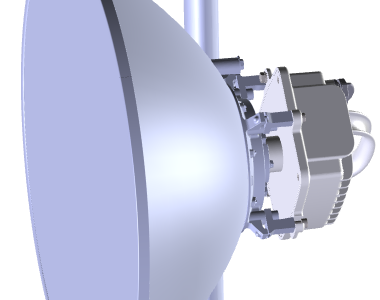
RAy3 link requires use of external parabolic antenna for each RAy unit – both for physical mounting as well as for the wireless transmission itself. Parabolic antennas from different producers are available.
| Important | |
|---|---|
Each antenna has to be equipped by a corresponding RAy antenna waveguide interface – the metallic pivot (28 mm diameter) with a rubber O-ring on it, otherwise the signal to/from the unit can not be transmitted from/to the antenna and such a link would not work. Before assembling RAy unit with antenna, always carefully lubricate both antenna waveguide pivot and RAy waveguide flange with thin layer of silicone grease to prevent the damage of O-ring and surfaces. Pivot fits smoothly in to the flange, if it is properly lubricated. A box with silicone grease is packaged with each delivery of new units – see Section 1.6.3, “Packaging”. |
| Note | |
|---|---|
If O-ring is injured or damaged, please exchange it immediately for a new one (size 22×2 mm, type ‘FPM80’), otherwise moisture + dust can leak into the waveguide and emitter. It may eliminate several dB of signal and cause a corrosion. Antennas from Jirous, LEAX Arkivator and Shenglu ordered for RAy mounting are automatically equipped by RACOM RAy waveguide interface and are ready for mechanical fixing of RAy unit to the antenna. Antennas from other vendors has to be equipped by a proper antenna adapter first. The adapter must be mounted on the antenna before the RAy unit can be mounted on it. All available antennas and adapters are listed on RAy web pages in section Accessories > Antennas. |
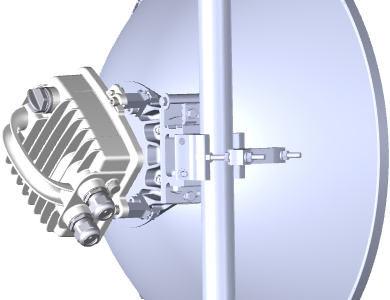
RAy unit is mechanically fixed to the antenna by 4× M8 screws (one per each side of RAy unit).
Installation and basic adjustment of the antenna is described in the
Section 4.2, “Antenna mounting”. Attaching RAy unit to it by 4× M8×30 (Allen)
screws delivered with each antenna or each mount kit is described in the Section 4.3, “RAy Unit mounting”. For adjusting the exact antenna direction see Section 4.7.2, “Directing antennas” .
| Note | |
|---|---|
Antennas from Jirous, LEAX Arkivator and Shenglu ordered for RAy mounting are automatically equipped for mechanical fixing of RAy unit (including the delivery of 4× M8×30 Allen screws). Adapters for antennas from other vendors always contain proper mechanical fixing of RAy unit (including the delivery of 4× M8×30 Allen screws). The adapter has to be mounted to the antenna first, the RAy unit is then mounted on this adapter. All available antennas and adapters are listed on RAy web pages in section Accessories > Antennas. |
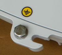
Grounding screw is used for a proper grounding of the RAy unit, which is necessary for its function (ensured by galvanic connection to the grounded mast through a grounding cable).
One M8 screw (with standard 6-edge head) is delivered with each RAy unit.
Grounding screw has two possible positions (two holes) to be mounted in. Those are located
near the left and right fixing screws of the RAy unit and both are marked by a
yellow grounding symbol ![]() and both are equivalent (second hole remains unused). For more information about unit grounding see Section 4.3.3, “RAy unit grounding”.
and both are equivalent (second hole remains unused). For more information about unit grounding see Section 4.3.3, “RAy unit grounding”.
| Note | |
|---|---|
Grounding screw function is to ensure proper grounding of the RAy unit (by a grounding cable), not for mechanical fixing of the unit. |
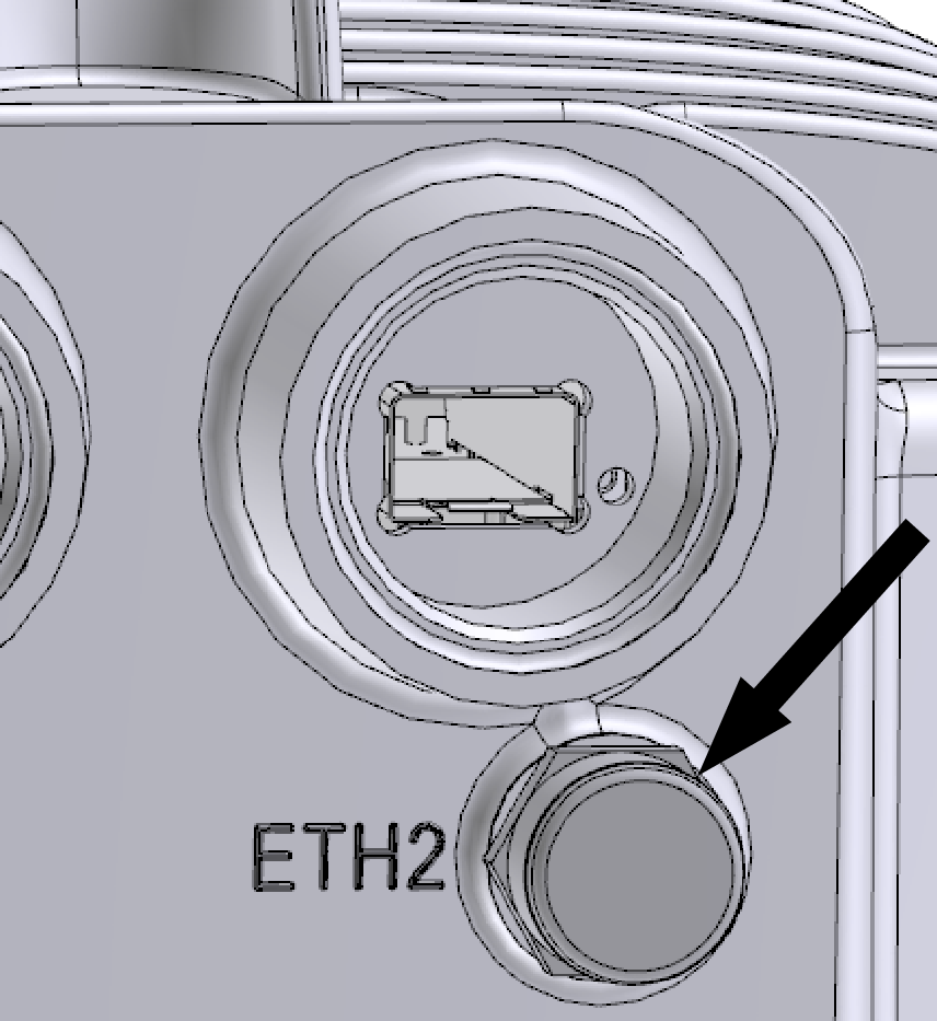
Pressure equalization between outside and inside of RAy unit is an important technical requirement. It is realized by a small plastic screw next to ETH2 label. It ensures the pressure equalization without letting moisture or humidity to enter the unit.
| Important | |
|---|---|
Do not manipulate or remove this small plastic screw. It is part of the cabinet and its manipulation or a deformation can damage the water protection of the unit. Warranty does not apply for units with this screw missing or deformed. |
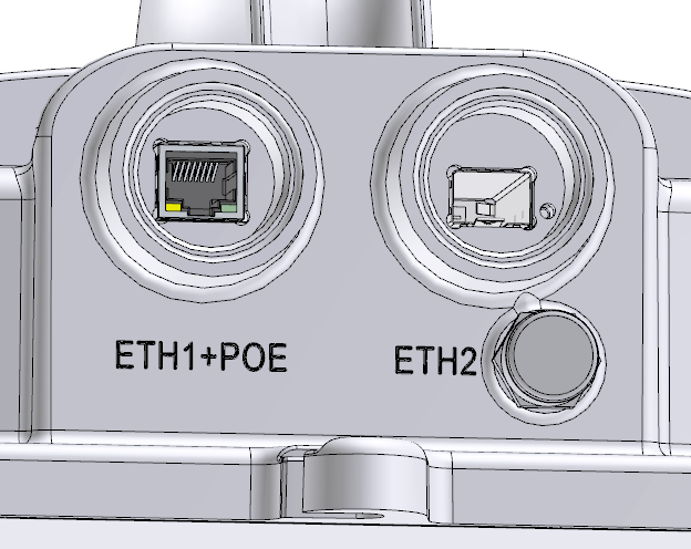
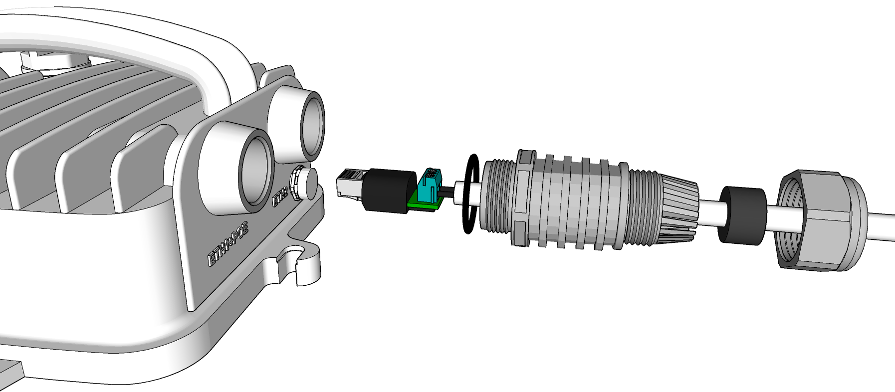
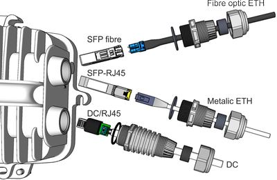
This chapter describes interfaces for user data transfer and power sourcing of the unit, as described on the picture and characterized in the table below. Remaining interfaces for service purposes are described in next chapter Service interfaces.
| Slot | Function | |
| ETH1+POE | Gigabit metallic Ethernet + Power over Ethernet (PoE) port | |
| This port is capable of powering the unit with active or passive PoE power source or with direct DC. | ||
| ETH2 | Slot for user exchangeable SFP module | |
| A wide range of fibre optics Ethernet modules is available. Both single or dual mode transceivers can be used. SFP module with metallic RJ45 interface can also be used. | ||
| The SFP LED | ||
| Located on SFP, just next to connectors. It is controlled by SFP module. Its function is specific for each SFP module. The typical behavior is an indication the received signal from the optical or metallic link to be within operational range. | ||
| Note | |
|---|---|
A set of all necessary bushing parts are delivered with each RAy unit – see a description of this standard basic accessory ACS-RAy3. Additional bushing options for installation of longer connectors or other equipment are available as well. For bushings installation see Section 4.4, “Connectors assembly and disassembly”. |
| Important | |
|---|---|
All bushings and plugs (including the original plugs in the flanges) must be fitted with O-rings and carefully tightened. Otherwise, the unit is not protected against moisture intake through connectors and cannot offer guaranteed functionality. |
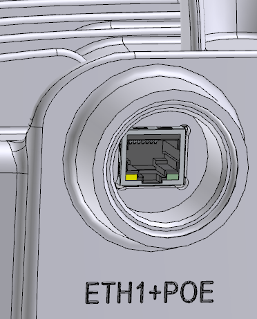
RJ45 socket connector marked „ETH1+POE“ is a standard 10/100/1000 Mb/s metallic Ethernet port.
This port is also used for power sourcing the unit by PoE (Power over Ethernet) or direct DC power source. Both an active PoE power supply (compliant with IEEE 802.3at respectively IEEE 802.3bt standards known also as PoE+ respectively PoE++) and a passive PoE power supply (with wider voltage range than PoE) are supported.
Supported PoE types of power sourcing are:
Active PoE requires PoE power supply compliant with standards IEEE 802.3bt or IEEE 802.3at (the second one only for RAy3-17 and RAy3-24) and the reasonably quality Ethernet cable, otherwise the proper function of the unit can’t be guaranteed. The norm defines supplied voltage in the range 37-57V (for PoE+) respectively 51-57V (for PoE++) and max. current typically 0.55-2.0 A.
Passive PoE can operate in extended voltage ranges which depends on the maximum power consumption of each model:
20 to 60 V for 10, 17 and 24 GHz units (for unit boot at least 21 V to prevent booting with discharged 24 V battery)
37 to 60 V for 11, 18 and 80 GHz units
Any polarity of DC and PoE inputs are supported.
| Note | |
|---|---|
Extended voltage ranges and polarities are identical with direct DC power sourcing described in Section 1.3.3, “DC power (using ETH1+POE)”. Maximum long-term voltage on the unit is recommended to be below 58 V (to ensure over-voltage protection inside the unit stays deactivated). |
RJ45 connector pins are wired according standards IEEE 802.3bt (utilizes 4 pairs = 8 wires) and IEEE 802.3at (utilizes 2 pairs = 4 wires). All units support all PoE modes of operation:
Mode A: pins 1,2 (V+) and 3,6 (V-)
Mode B: pins 4,5 (V+) and 7,8 (V-)
Mode A+B: all 8 pins with numbers identical to Mode A and Mode B
| Note | |
|---|---|
Additionally to IEEE norm all units can be powered by PoE or DC with opposite +/- polarity. PoE with 8-wires is strongly recommended for 10, 11, 18 and 80 GHz units due to their power consumption >25 W. PoE with 8-wires is recommended also for other models to minimize the energy lost in the Eth cable (it lowers the resistance of the Eth cable to half compared with 4-wires PoE). |
Galvanic separation: All contacts of RJ45 connector are galvanically separated from RAy unit. It ensures galvanic separation for any kind of PoE power supply as well as for DC power sourcing (made through OTH-DC/RJ45).
| Important | |
|---|---|
The shielding of the Ethernet cable has to be properly grounded near the unit to ensure proper unit connectivity and resistance against over-voltage. Suitable grounding kit (for example items GND-CAT7 or GND-CAB-UNI or similar) has to be applied and connected to the mast or to the Grounding screw on the well grounded unit chassis (for example by the item GND-RAy). More information about usage and installation of available power options can be found in Section 4.6, “Power supply” and Section 4.5, “Grounding and overvoltage protection”. |
| Note | |
|---|---|
One plastic RJ45 plug for CAT5e and CAT6 cables is delivered with each unit (within item ACS-RAy3), ready to be punched to an Ethernet cable. Higher quality and CAT7 compatible RJ45 plugs are available to be purchased as well (for example item CON-RJ45-CAT7). |
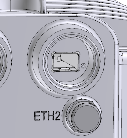
„ETH2“ is a standard SFP slot for 10/100/1000/2500 Mb/s Ethernet SFP modules, user exchangeable. (Legacy 10-24GHz RAy3 units produced before January 2024 do not support 2500 Mb/s Eth SFP modules, even with FW 2.0.14.0 or later.) In the case of 80 GHz unit the SFP slot supports also SFP+ standard, so 2.5/5/10 Gb/s SFP+ modules can be used as well. It is typically used for second Ethernet data and/or management connection to the unit. In the case of RAy3-80 unit the SFP+ slot is typically a primary data port (and sometime also a primary management port), because it is the only Ethernet interface on the unit which is able to support higher speeds than 1 Gb/s.
Both fibre optic and metallic Ethernet SFP and SFP+ modules are supported. For optical both single and dual mode fibre optics Ethernet modules (= 2 or 1 fibres) can be used. CSFP/CSFP+ modules are not supported. offers just the basic set of mentioned types of SFP and SFP+ modules, as a standard RAy accessory. has carefully selected and tested all offered SFPs according to high long-term stability in all temperatures, low power consumption and other technical parameters important for users and they are guaranteed to function with RAy units in all situations and temperatures.
The SFP/SFP+ status LED is located just next to the slot. It is controlled by the SFP/SFP+ module and its function is specific for each such a module. The typical behavior is an indication the received signal from the fibre optic or metallic link to be within operational range.
| Important | |
|---|---|
SFP/SFP+ module has to be inserted to out-of-power unit, otherwise its function is unpredictable and the module and/or the unit can be damaged. Do not remove the smaller plastic screw next to ETH2 label. It is part of the cabinet and assures pressure equalization outside and inside. |
| Note | |
|---|---|
Other types of standard SFP/SFP+ modules with industry temperature range (at least -30 °C to +85 °C) and with adequate power consumption can be used as well, but cannot guarantee their complete compatibility with RAy units. is not responsible for any issues arising from the use of different SFP modules. Following requirements needs to be met by any third-party SFP/SFP+ module inserted into RAy3 unit:
|
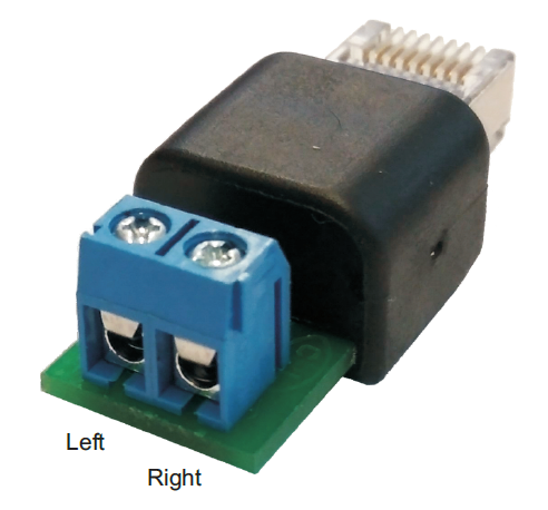
Direct DC power source can be used to power the RAy3 unit. Instead of standard DC connector the DC cable is mounted to a terminal block on DC/RJ45 adapter (item OTH-DC/RJ45). The adapter is then fitted in to the RJ45 connector in slot ETH1+POE.
Item OTH-DC/RJ45 is orderable with the unit
(see Section 1.7.1, “RAy units”). It is equipped by 2 terminals (each max.
2 A / 1.5 mm2 / AWG 14) with screws to ensure perfect connection
with cooper DC power cable.
Internal RJ45 pins wiring of DC/RJ45 adapter
utilizes all 8 contacts on RJ45 and is:
DC terminal (+) RJ45 pins: 1,2,4,5
DC terminal (-) RJ45 pins: 3,6,7,8
RJ45 shield floating (not connected to any pin)
Both polarities are supported. Supported voltage range depends on the maximum power consumption of each model. Those are:
20 to 60 V for 10, 17 and 24 GHz units (for unit boot at least 21 V to prevent booting with discharged 24 V battery)
37 to 60 V for 11, 18 and 80 GHz units
Maximum long-term voltage on the unit is recommended to be below 58 V (to ensure over-voltage protection inside the unit stays deactivated). Power input is galvanically separated inside the unit.
| Important | |
|---|---|
The optional shielding of the DC cable has to be properly grounded near the unit to ensure proper resistance against over-voltage. Suitable grounding kit (for example item GND-CAB-UNI or similar) has to be applied and connected to the mast or to the Grounding screw on the well grounded unit chassis (for example by the item GND-RAy). More information about DC power sourcing installation can be found in Section 4.6, “Power supply” and Section 4.5, “Grounding and overvoltage protection”. |
| Note | |
|---|---|
DC-RJ45 adapter occupies ETH1+POE port. When used, Ethernet connection to the unit has to be made through SFP module inserted in to ETH2 port. Standard SFP/SFP+ modules for fibre optic Ethernet or for metallic Ethernet (with RJ45 connector) can be used – see Accessories / SFP modules for more details. Other valid possibility how to power the unit using DC power source is to use passive PoE injector or active PoE power supply with DC input and deliver the power to the unit over PoE through Ethernet cable with RJ45 connector plugged in to ETH1+POE slot as described in Section 1.3.1, “RJ45 connector (ETH1+POE)”. |
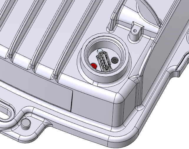
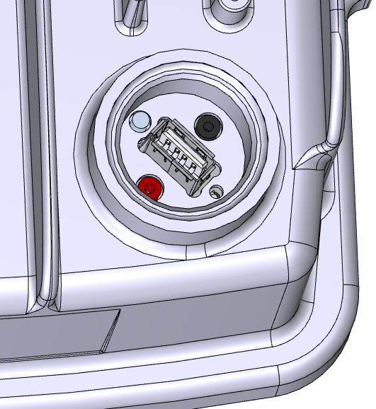
Slot „S“ stands for “Service”. It contains system connectors – standard USB port and a pair of contacts for RSS voltage output (red + gray ones). Also HW button and Status LED are located there.
| Slot | Function | |
| S | USB service connector | |
| For USB/WiFi or USB/ETH adapters, see Section 1.4.1, “USB connector ( S )” | ||
| RSS voltage output | ||
| Red and green connectors (for example 0.547 V means RSS = –54.7 dBm),
see Section 1.4.4, “RSS voltage contacts ( S )”. | ||
| HW button | ||
| For service purposes: Internal backup or Factory settings, see Section 1.4.5, “HW button ( S )” and section Default settings in Section 5.6.1.1, “Backup”. | ||
| Status LED | ||
| Visible through semitransparent plug, see Section 1.5, “Status LED ( S )” | ||
USB-A port is designed for access to RAy management through USB/WIFI adapter or USB/ETH adapter plugged in to. More information about installation and configuration of available adapters can be found in Quick Guide and in Section 5.4.3, “Service access” (part “USB Accessories”).
| Note | |
|---|---|
Only recommended adapters are supported. See USB adapters on RAy Accessories web site. |

Each RAy3 unit is equipped with the service WiFi interface from the factory. It is realized by standalone WiFi module inserted in to the USB connector in slot “S”. WiFi can be used solely for unit management (no user traffic can be transmitted by using this WiFi connection).
WiFi module can be disabled in FW (WiFi module is out of power then) or manually unplugged. In both cases the results are identical – no WiFi is possible. Management of the WiFi port is described in Section 5.4.3, “Service access” (part “USB Accessories”).
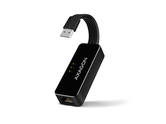
RAy3 unit can be equipped with the service Ethernet interface as an option. It can be used solely for unit management (no user traffic can be transmitted using this Ethernet connection).
Optional Eth adapter (see RAy Accessories USB adapters web for available types) can be inserted in to the USB connector in slot “S” (instead of WiFi module). Management of this Ethernet port is described in Section 5.4.3, “Service access” (part “USB Accessories”).
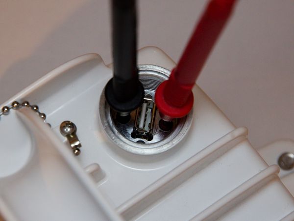
RSS voltage output connectors are located in slot „S“ aside USB connector. This pair of contacts (red + green ones) allows to connect a voltmeter (pin diameter 2 mm) to the RAy unit and measure RSS value transformed to the voltage output.
RSS (Received Signal Strength) is a basic parameter used for directing antennas to the optimal direction. RSS output voltage is calibrated to be proportional to actual RSS dBm (for example 0.547 V means RSS –54.7 dBm). Thus a standard digital voltmeter allows to see RSS value in a digital form interactively during the antenna alignment. More information about RSS voltage output usage is in Section 4.7.2, “Directing antennas” (part “Voltmeter”) together with several alternative ways to get this value by other methods.
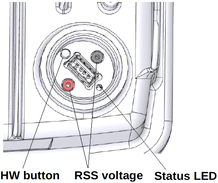
It is located in a small hole next to USB connector. It can be pushed by any tiny blunt thing with the diameter up to 2 mm. Its length has to reach about 7 mm in to the hole. (It can be ball pen cartridge – both ends work on the thin one, match, toothpick, etc.).
| Important | |
|---|---|
Usage of very sharp things for pushing the HW button (like needle, edge clip etc.) may destroy the contact inside RAy unit! Such a button destruction is not covered by warranty. |
The button supports multiple functions, which are activated dependent on the state of the unit when the button is pushed and the length of the push:
| Action to be performed | Unit status | Button pushed | SYS LED indication |
|---|---|---|---|
| Restore temporary stored customer settings (backuped previously to FLASH memory of the unit) | Normal operation | For 5 seconds | Flashes Green |
| Applying Factory settings
The entire set of parameters from the Link Settings and Switch settings menu tree is affected including user credentials. Once done, the unit reboots. | Out of power | Pushed before power on, released after SYS LED stops flashing red | Flashes Red (delayed after power on, for a duration of 5 seconds) |
| Note | |
|---|---|
Those actions and their use are described in detail in Section 5.6.1, “Maintenance”. |

RAy3 unit is equipped with one LED indicator located inside the housing of the
FOD unit in slot „S“ (during normal operation covered by semi-transparent plug). Meaning of
the color combinations of this LED indicator is:
| Green and
Red LEDs | Function |
|---|---|
|
| Unit is starting |
|
| Power source voltage is out of allowed range |
|
| System is up and working OK |
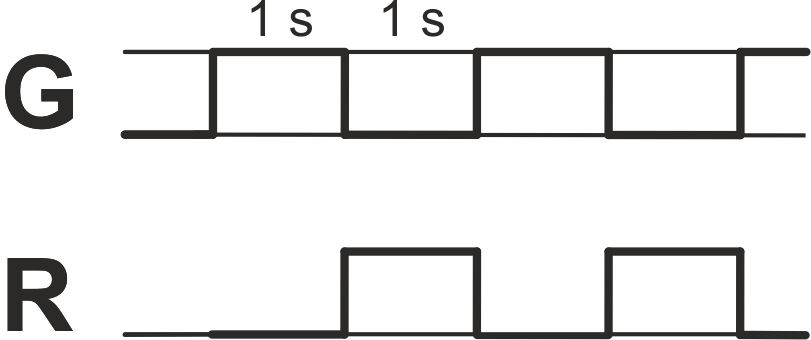 |
System reports warning or alarm, |
|
| System reports HW alarm |
|
| Unit is out of power or HW button pressed |
Outer sizes for all RAy3 models are identical:
245×245×160 mm
Weight:
RAy3-10 2.8 kg (6.2 lbs)
RAy3-11 2.9 kg (6.4 lbs)
RAy3-17 2.6 kg (5.7 lbs)
RAy3-18 2.9 kg (6.4 lbs)
RAy3-24 2.6 kg (5.7 lbs)
RAy3-80 2.8 kg (6.1 lbs)
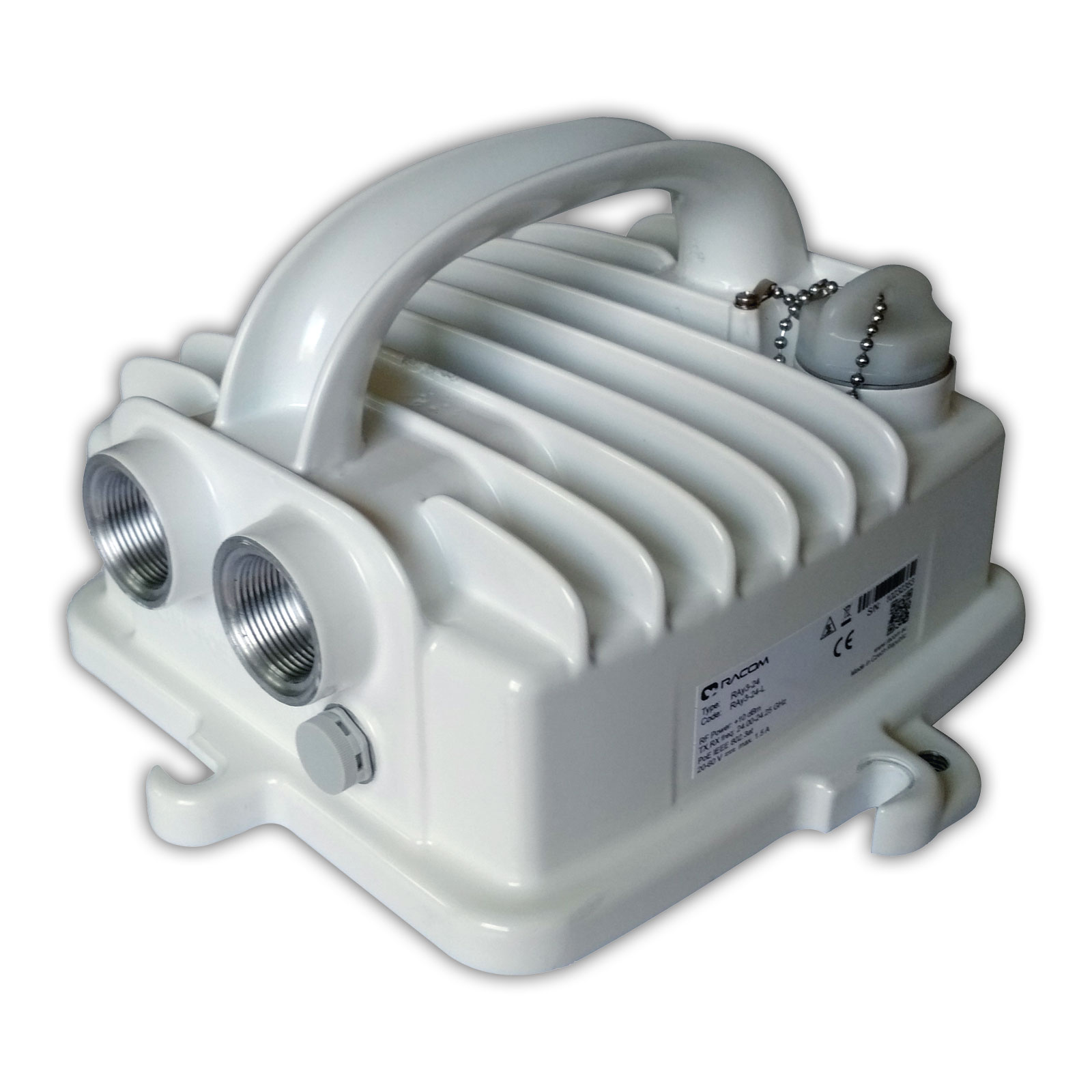
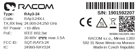
Basic technical parameters like identification of the HW model, working frequency, maximum RF Output power, requirements for power supply, most important certifications, etc. are visible on RAy Product label. All technical parameters are stated in detail in Chapter 9, Technical parameters.
The label contains identification of the HW model and its serial number, basic technical parameters, most important certifications, QR code to manual, address of the producer, etc. Meaning of the most important information listed on the product label is:
Type – RAy3 product line identification (for details see Section 1.7, “Ordering codes”)
Code – detailed identification of the unit HW (for details see Section 1.7.1, “RAy units”)
S/N – serial number, MW link consists of two separated units with two different serial numbers
QR code – www link to the latest version of the User manual
RF Power – maximum output power
TX, RX freq – range of working frequency
PoE – power supply characteristics
CE, FCC ID, IC or other – available certifications
| Important | |
|---|---|
The processor included in the unit variant S and X (identified by the item ‘Code’ on product label and in the ordering code) uses an encryption module listed as 5A002.a.1 in the Regulation (EU) 2021/821, setting up a Community regime for the control of exports, transfer, brokering and transit of dual-use items. Units are subject to export control when exporting outside the European union, according to national, EU and US law. |
| Note | |
|---|---|
A link should consist from a pair of “-L” and “-U” units (L and U are always a last letter in Code printed on product label of each unit), but it is not mandatory for RAy3-17 and RAy3-24 (for those models HW for L and U unit is identical and L/U settings could be assigned by SW). Using L + U pair ensures all default settings of both units match each other (including proper IP addresses as described in this manual). It ensures the link is automatically established when received from the factory or after applying Default link settings or Factory settings (to simplify initial setting of the whole link). |
The RAy3 radio link is supplied in a package containing two separate boxes. Delivery includes:
2 pcs RAy3
2 pcs Cable bushing set ACS-RAy3 (bushings and connectors)
1 pc SILICONE GREASE
If only one unit is delivered, then delivery includes one piece of each item.
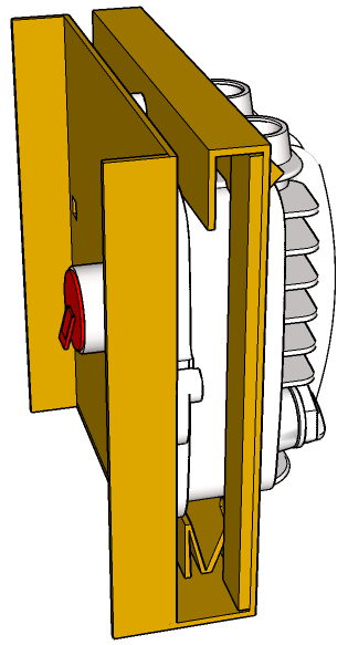
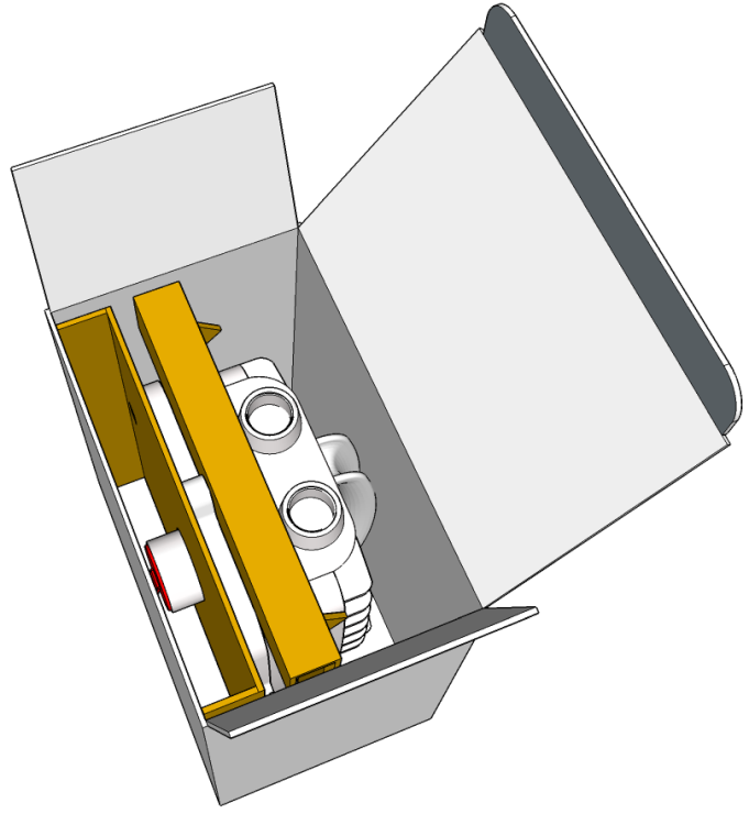
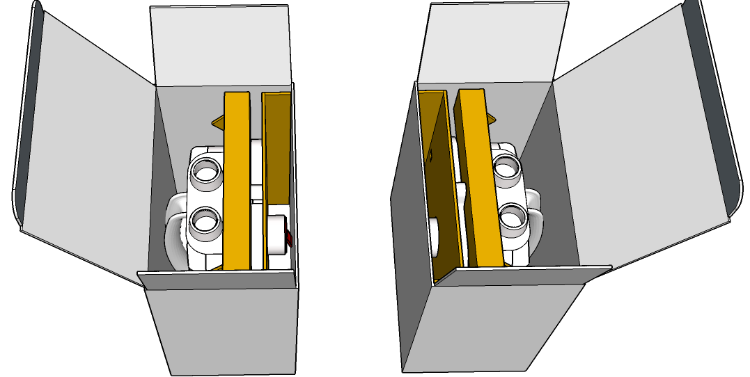
The unit is fixed in the box as follows:
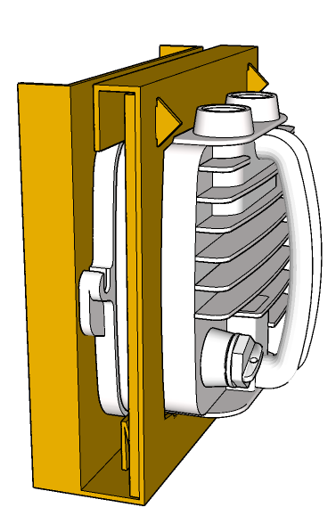

| Note | |
|---|---|
Two separate boxes in the common package are turned such that both waveguides are heading to each other. It allows to automatically establish a link between delivered RAy3 units without unpacking them from the box. See Quick Guide, step 4 or Chapter 3, Step-by-step Guide. |
Single unit packaging
Outer sizes for all RAy3 models are identical:
29×28×18 cm
Weight:
RAy3-10 3.4 kg (7.5 lbs)
RAy3-11 3.5 kg (7.7 lbs)
RAy3-17 3.2 kg (7.1 lbs)
RAy3-18 3.5 kg (7.7 lbs)
RAy3-24 3.2 kg (7.1 lbs)
RAy3-80 3.4 kg (7.4 lbs)
Double unit packaging
Outer size:
38×32×29 cm
Weight:
RAy3-10 7.2 kg (15.9 lbs)
RAy3-11 7.4 kg (16.3 lbs)
RAy3-17 6.8 kg (15.0 lbs)
RAy3-18 7.4 kg (16.3 lbs)
RAy3-24 6.8 kg (15.0 lbs)
RAy3-80 7.1 kg (15.6 lbs)
RAy3 units are ready for direct mounting to:
Jirous Class 3 or Class 2 antennas (Jirous Antennas)
LEAX-RAy Class 3 antennas (LEAX ARKIVATOR TELECOM website)
Shenglu-RAy Class 3 antennas
| Note | |
|---|---|
Jirous Class 3 antennas (type JRMC in Ordering code) smoothly replaced Jirous Class 2 antennas (types JRMA or JRMB in Ordering code) in portfolio of antennas during Q1/2020. |
Individual datasheets with exact sizes and weights are accessible on website.
Standard antennas shipment is one antenna in its own box. is able to arrange more compact shipment for a bigger amount of antennas (on a special request).
Tab. 1.1: Overview of Jirous Class 3 antennas
| Bands | ||||
|---|---|---|---|---|
| 10, 11 GHz | 17, 18 GHz | 24 GHz | 80 GHz | |
| diameter [m] | gain [dBi] | gain [dBi] | gain [dBi] | gain [dBi] |
| 0.4 | 29.5-30.5 | 34.6-35.6 | 37.4 | 46.4-48.2 |
| 0.68 | 34.1-36.0 | 38.6-40.0 | 42.0 | 50.7-51.6 |
| 0.9 | 37.0-37.5 | 41.4-42.5 | 44.0 | – |
| 1.2 | 40.0-41.0 | 43.2-44.7 | 46.0 | – |
| 1.8 | 43.0-44.0 | – | – | – |
Tab. 1.2: Overview of LEAX-RAy antennas
| Bands | ||||
|---|---|---|---|---|
| 10, 11 GHz | 17, 18 GHz | 24 GHz | ||
| nominal diameter [m] | dish diameter [m] | gain [dBi] | gain [dBi] | gain [dBi] |
| 0.3 | 0.37 | 29.0-30.1 | 33.7-34.7 | 36.9 |
| 0.6 | 0.66 | 34.1-35.2 | 39.4-40.5 | 42.0 |
| 0.9 | 0.98 | 37.5-38.5 | 42.4-44.1 | 45.4 |
| 1.2 | 1.29 | 40.3-41.7 | 44.7-45.7 | 47.9 |
Tab. 1.3: Overview of Shenglu-RAy antennas
| Bands | ||||
|---|---|---|---|---|
| 10, 11 GHz | 17, 18 GHz | 24 GHz | ||
| nominal diameter [m] | dish diameter [m] | gain [dBi] | gain [dBi] | gain [dBi] |
| 0.3 | 0.38 | 28.7-30.0 | 33.3-34.6 | 36.5 |
| 0.6 | 0.66 | 33.5-35.0 | 38.4-39.6 | 41.5 |
| 0.9 | 1.02 | 37.8-39.0 | 42.3-43.5 | 45.4 |
| 1.2 | 1.30 | 40.2-41.0 | 44.0-45.1 | 46.6 |
| 1.8 | 1.89 | – | 47.1-48.2 | – |
Andrew (Class 2 or 3 or 4) or traditional Arkivator antennas or antennas from other suppliers can also be used, but they require an antenna mounting kit. Flexible waveguide is a general-purpose option for any antenna usage. Contact us for available types and details.
Antennas and other accessories are necessary for RAy units to allow a proper functionality of the whole microwave link.
always tries to ship all ordered accessories together with RAy units and antennas. Accessories are mostly small items, so typical packaging is that all accessories are shipped on the same palette with other material (within one additional RAy box).
All RAy3 models mentioned in this manual have their unique ordering codes. Available are also capacity keys, feature activation keys and accessories necessary to reach expected functionality of the link. All ordering codes are discussed in detail in this chapter and at web, and are available for purchase at E-shop.
| Note | |
|---|---|
Ask your supplier to ensure completeness of your product delivery for the individual link situation, applicable spectrum regulations, local safety and security requirements, type of power sourcing, grounding, etc. |
| Important | |
|---|---|
does not have any responsibility for improper use of any offered device. It is customers full responsibility to check technical parameters of all ordered items and to use and configure them in accordance with their purpose. It is also customers full responsibility to respect all requirements applicable at the site of installation. |
RAy ordering codes begin with a string printed on Product label (9-11 characters long, lasting by „-L“ or „-U“). It defines HW parameters and factory settings, which cannot be changed later on (like working frequency, encryption HW support, factory defaults and limitations built in to units in the factory like limitation of RF Output power or prevention to use any form of encryption). Rest of the ordering code defines functionalities and options which could be added, erased or changed by a user later on (like SW feature key for initial capacity or an optional DC power adapter).
Ordering Code structure:
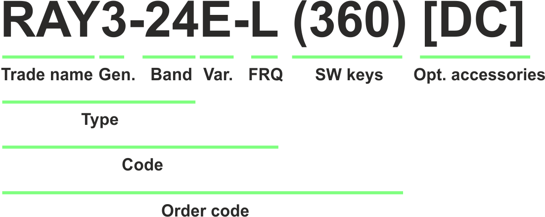
Trade name – trade and marketing name of the product. This name is used for all products within the same product family.
Possible values: RAy
Gen. – generation of the product of specific Trade name. The very first generation does not have any number in this position.
Possible values: none, 2, 3
Current generation is RAy3. Order codes for legacy products (Gen. 1 or 2) – see RAy User manual or RAy2 User manual.
Band – frequency band in GHz
Possible values: 10, 11, 17, 18, 24, 80
Var. – designation of product variant. More variants can be used within one unit, i.e. more letters can be on this position. These variants are fixed in unit HW and cannot be changed later on.
Possible values:
E – Data encryption possible.
N – Data encryption never possible.
R – reduced RF output power -30 to -15 dBm, for RAy3-24 only (always in combination with encryption letter E, N).
Legacy values:
none (position not used) – means same as X
X* – encryption HW support (under production until III/2021; see export restriction below)
S* or XS* – encryption HW support, MTU limited to 2048 Bytes (under production until III/2019; see export restriction below)
FRQ – frequency
Possible values:
L or U – unit transmits on Lower (L) or Upper (U) part of the band
When ordering a link, order one L unit and one U unit – see Note below for more info.
A or B or C – sub-band for some frequencies (like RAy3-10, RAy3-11, RAy3-18)
Two letters (L/U and A/B/C) are used then.
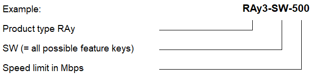
SW keys – if unit is ordered with SW keys, those are specified in this bracket. Every SW key can be ordered independently for specific unit S/N anytime later on. Part No‘s are different depending on whether the key is ordered with the unit or later.
Possible values:
360 or 500 or 1000 (except RAy3-80) or 2000 (RAy3-11 only).
Default Data speed is 360 Mb/s for all units.
Part No.: RAy3-SW-360; optional 500 Mb/s, Part No.: RAy3-SW-500; optional 1000 Mb/s, Part No.: RAy3-SW-1000
1G or 2.5G or 5G or 10G (RAy3-80 only).
Default Data speed is 1 Gb/s for all units.
Part No.: RAy3-SW-1000; optional 2.5 Gb/s, Part No.: RAy3-SW-2500; optional 5 Gb/s, Part No.: RAy3-SW-5000; optional 10 Gb/s, Part No.: RAy3-SW-10000
Power (RAy3-11, RAy3-18, RAy3-80 only)
Enables full RF Output power of the unit (otherwise max. ʿTX powerʾ is +10 dBm).
Part No.: RAy3-SW-POWER
Encryption (except RAy3-80)
Enables AES encryption.
Part No.: RAy3-SW-ENCRYPTION
Opt. accessories – if unit is ordered with optional accessories, those are specified in this bracket.
Possible values:
DC – DC/RJ45 power adapter, Part No.: OTH-DC/RJ45
Type – specific product type for which type approvals like CE, FCC etc. are issued
Possible values:
RAy3-10, RAy3-11, RAy3-17, RAy3-18, RAy3-24, RAy3-80
Code – detailed HW identification of the unit printed on Product label on the housing.
SW keys and Optional accessories are not HW dependent and can be installed or de-installed later on, so they are not printed on Product label.
Order code – the complete product code, which is used on Quotations, Invoices, Delivery notes etc.
In order to find out the correct Order code, please use E-shop.
| Important | |
|---|---|
* Export restrictions: The processor included in the unit variants ‘X’ and ‘S’ uses an encryption module listed as 5A002.a.1 in the Regulation (EU) 2021/821, setting up a Community regime for the control of exports, transfer, brokering and transit of dual-use items. Units are subject to export control when exporting outside the European union, according to national, EU and US law (ECCN 5A002.a.1). In the case of export from the country where the units were originally delivered by RACOM, the exporter must inform RACOM of the new country of delivery. |
| Note | |
|---|---|
RAy3-17, RAy3-24 – the same HW for Lower (L) and Upper (U) unit. L/U is used, but indicates only factory defaults for TX/RX frequencies and other parameters which needs to be different for each side of the link. All these parameters can be changed in the management (including changing L to U and vice versa). All other RAy3 – different HW for Lower (L) and Upper (U) unit. Selecting the pair of Lower (L) and Upper (U) units for a link allows the link to be established without any initial manual settings – just by powering up both units at factory defaults (see Quick guide or Chapter 3, Step-by-step Guide). |
RAy units allow to pay only for purchased transmission capacity (pay as-you-grow concept). Activation keys could be purchased together with the unit or later at E-shop. Each key is generated for specific S/N of the unit and the purchased capacity. Once installed, it unlocks all combinations of channels and modulations up to the purchased capacity. SW keys could be erased or upgraded. See Section 5.6.1.2, “SW feature keys” for more details.
For allowed combinations of channel width and modulation for transmitting channel see Capacity SW keys table. The Capacity limit applies for transmitted data on the unit where the key is installed. SW keys for capacity could be different for each side of the link – for example if the link is expected to be configured for asymmetrical capacity.
Several types of SW feature key are available for RAy units:
Bundled capacity (ordered together with RAy units – see previous chapter)
Separately purchased capacity SW keys (see below)
Upgrade capacity SW keys (see below)
| Note | |
|---|---|
is able to generate customer specific Capacity SW keys on special request. |

RAy units allow to pay only for purchased features (pay as-you-grow concept). Activation SW keys could be purchased together with the unit (as described in Section 1.7.1, “RAy units”) or later at E-shop or by a special agreement. Each SW key is generated for specific S/N of the unit and the purchased feature (or a set of features). Once installed, a specific feature or function of the unit is allowed. SW keys could be erased or upgraded. See Section 5.6.1.2, “SW feature keys” for more details.
Available SW feature activation keys are listed in following table:
Tab. 1.6: SW keys overview
| RAy3 | Ordering codes for feature activation keys | |||
|---|---|---|---|---|
| Ordering code |
Meaning |
Parameters |
Without key | Note |
| RAy3-SW-xxx | Limitation of Speed | xxx: value of speed in Mb/s | RAy3-10, 17, 18: < 3 Mb/s RAy3-11: 4 Mb/s RAy3-80: 25 Mb/s | |
| RAy3-SW-POWER |
Unlimited RF Output power |
– | RAy3-10: -15 to +10 dBm RAy3-11, 18: -1 to +10 dBm RAy3-17, 24: -30 to +10 dBm RAy3-80: -6 to +10 dBm | only
RAy3-11, RAy3-18, RAy3-80 |
|
RAy3-SW-TX-xyy |
Limitation of | x: P = positive value N = negative value yy: value of limit in dBm | RAy3-10: -15 dBm RAy3-11, 18: -1 dBm RAy3-17, 24: -30 dBm RAy3-80: -6 dBm | not in E-shop (Special agreement needed) |
|
RAy3-SW-ENCRYPTION |
Allow AES encryption | – |
Encryption disabled | not in E-shop (Special agreement needed) |
| ver 1.0 |
| Note | |
|---|---|
Units with variant ‘N’ in the Code printed on Product label would never allow to use encryption, even if such a SW key is purchased and installed to the unit (‘N’ prevails). |
Ordering codes for all accessories offered by to allow a proper functionality of the whole microwave link are listed on Accessories section of RAy web site and they are available for purchase in E-shop. More information about accessories can be also found in Chapter 2, Accessories.
| Note | |
|---|---|
Please consult your supplier to ensure completeness of your product delivery for the individual link situation, spectrum regulations, local security requirements, type of power sourcing, grounding, etc. |