Connection and configuration of the active RipEX unit inside of RipEX-HS is the same as for
standard RipEX. Use either X5 – ETH/USB adapter
( https://www.racom.eu/eng/products/m/ripex/bench-test.html#connect-PC) or Ethernet
interface where RipEX access defaults are: IP 192.168.169.169/24, username: admin, password:
admin Inactive RipEX unit can be reached only via X5 adapter.
For more details see chap. Getting started.
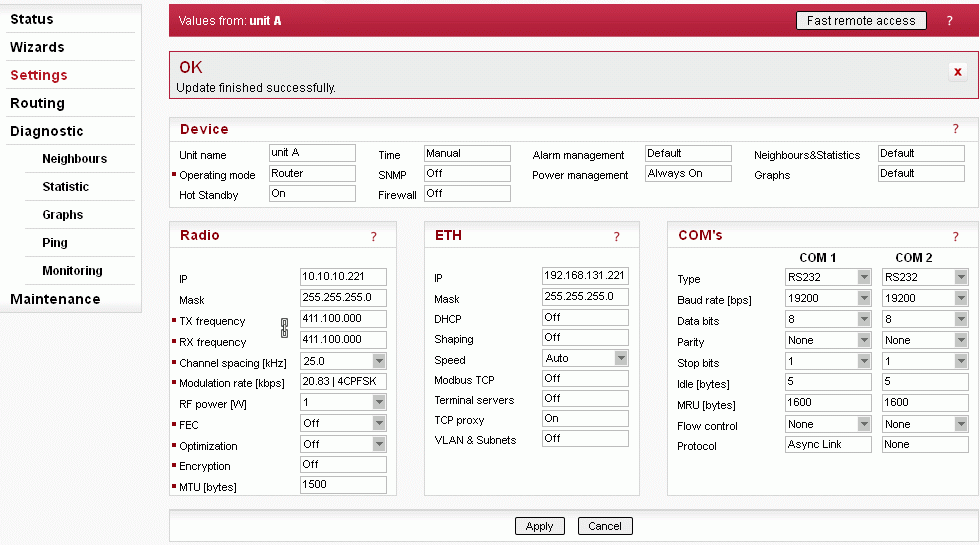
The settings of all parameters have to be identical. The only exception is the Unit name – it shall be different and preferably contains A character A for unit A and character B for unit B (e.g. Unit A).
To be sure that the setting of both units are identical it is recommended to set unit A, thereafter save the settings to a file (Maintenance -Configuration – Save to file) and use this setting for unit B (Maintenance -Configuration – Restore – File path – Upload) and change the Unit name.
| Note | |
|---|---|
Be careful to set RipEX units inside of RipEX-HS to their factory defaults. If you do that, both units will have the same Ethernet IP address and their Operating mode is Bridge. While configuring you could be accessing the second unit over the air without being aware of it. In such a case use X5 – ETH/USB adapter. |
When RipEX unit is used in RipEX-HS and Hot Standby is „On“ there are some limitations with it. Specifically, CD pin on COM1 and HW alarm Input and Output are used internally and not available to the user. Neither Save nor Sleep modes can be activated. Please refer RipEX-HS User manual.
All settings below are valid only for RipEX units in RipEX-HS equipment, where two units
in Hot Standby mode are running. Both units MUST have the same settings! Only Unit names
should be different as this parameter is used in SNMP to recognize the sender of SNMP traps.
In order to ensure that the settings of both units are identical, it is recommended to set
unit “A”, thereafter save its settings into a file (Maintenance/Configuration/Save to file)
and use these settings for unit “B”. (Maintenance/Configuration/Restore/File path/Upload)
Finally, a unique Unit name should be assigned to Unit B.
List box: Off,
On
Default = Off
When “On”, HW switching from RipEX unit “A” to
RipEX unit “B” is performed based on the HW Alarm Output settings in Settings/Alarm
management. RipEX “A” is the primary unit, , Unit “B” is activated if there is HW alarm on
unit “A” or unit “A” power source is down or when Auto Toggle Period expired. When mentioned
events passed, RipEX “A” goes to be active again.
MAC
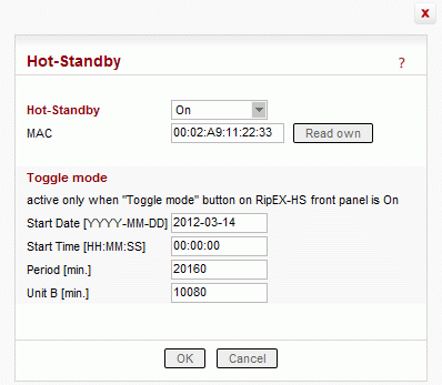
Both units in RipEX-HS are using the same MAC addresses (MAC cloning). Whichever unit is active (either “A or B”), RipEX Ethernet interface will use this MAC address. This MAC address has to be unconditionally set to the same value in both units used in RipEX-HS. Otherwise, the switching between units will not function properly.– it is possible to download the MAC address of this unit. The value in the second unit has to be manually set to the same value then
Auto Toggle mode
When Auto Toggle mode is On (HW button on front panel), controller automatically switches-over to RipEX ”B“, even if “A” doesn’t have any alarm and uses “B” for a set time in order to confirm that RipEX ”B“ is fully ready-to-operate.Start Date [YYYY-MM-DD]
Fill in the Date in the required format when Auto Toggle mode starts.Start Time [HH:MM:SS]
Fill in the Time in the required format when Auto Toggle mode starts on ”Start Date“ day.Period [min.]
Minimum value 60 min.
Within this period units “A” and “B” will change their activities over. Unit “A” starts to operate at “Start Date and Time”. When “Period” minus “Unit B” time expires, controller switches to unit “B”.Unit B [min.]
Minimum value 5 min.
Time when unit “B” will be active within “Period”. It has to be shorter than Period by 5 min.
In the example above (Section 5.1.1, “Hot Standby – set to On”) a toggle will cause changing the active unit once per week (10,080 minutes) at midnight with the first week is starting on the date set above.
You can set the alarms to cause a switch-over to the hot-stand-by unit.
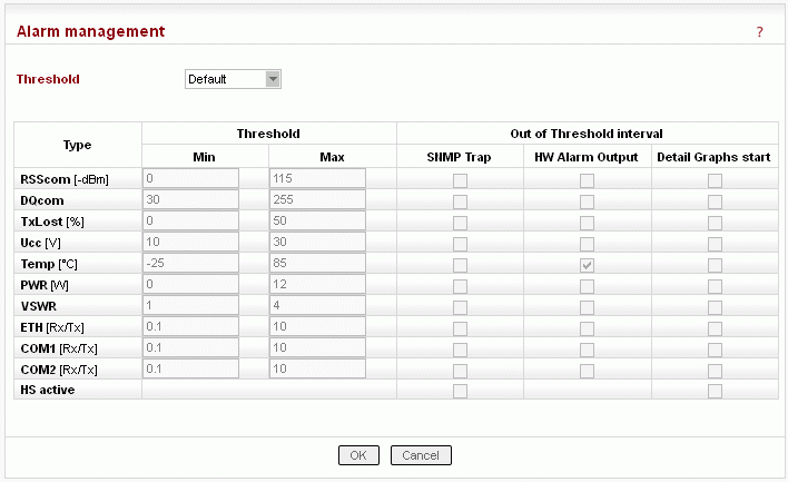
Enabled HW Alarm Output will be used for switching from this active unit to the inactive one, when the specific value is detected outside the Min Value – Max value range alarm will be declared and switching process is started.
Thresholds shall be set according the needs of the actual network:
RSScom | Max value shall be set to the designed RSS value plus a designed fade margin (e.g. 80+20 dBm), Min value can be 0 – stronger signal typically will not cause problems. |
DQcom | more significant communication troubles start with values less than 100; all values above should be sufficient RSScom and DQcom shall together indicate even partial damage or problem with RipEX unit receiver parts or coaxial feedline cable or antenna. Equally, the problem can be on the transmitter part of RipEX unit, coaxial feedline cable or antenna of transmitter counterpart(s). |
TXLost | the value will indicate problems with packet deliveries to communicating parties. It is cumulative percentage of lost packet on Radio channel (acknowledge has not been received). Applicable only in Router mode. Exercise caution when setting this alarm. Keep in mind, that problems of counterpart unit(s) can also be reflected here. E.g. counterpart doesn’t receive packets or doesn’t transmit acknowledges. Min value shall be set to 0, Max value to tens of % (e.g. 50). |
Ucc | since power supply for RipEX unit is controlled independently, this alarm is not recommended to be used for switch-over to Standby unit. However it can be used for SNMP trap informing about main power failure and switch to battery back-up. Min value shall be set to lower than 24.5, Max value to the maximal voltage limit for charging the battery (e.g. 29). |
Temp | the temperature of both RipEX units inside of RipEX-HS will probably be the same, so it doesn’t make any sense to use this alarm for switch-over. However this alarm can be used in case of hard duty cycle for switching between both units; Max value in such a case should be set approximately to 65. |
PWR | this value shall be set to a set value of power with a margin of ± 25-30%. Alarm will be active in case of faulty transmitter part of active RipEX. |
VSWR | this value mostly indicates problem with antenna or antenna feed line coaxial cable. When RipEX-HS-xO (one antenna switched for A and B units), a switch-over to unit B will probably not help. Recommended values vary between 1 and 3. |
ETH[Rx/Tx], COM1[Rx/Tx], COM2[Rx/Tx] | these three values represent No of received/transmitted packets on respective interfaces. They are mainly applicable for polling type applications network. Each communication has got one request and one reply, so the number of Rx and Tx packets should then be the same (Rx/Tx=1) . these alarms should not be used For report by exception networks. |
In the same window (Section 5.3, “Alarm settings”) one can set whether a SNMP trap should be sent when respective alarm occurs.
If both SNMP Alarm and HW alarm outputs are set for the same event the switch-over to the second RipEX unit will be carried out and the RipEX with alarm itself has no time for sending the SNMP trap out. Only events set on the Alarm management window and not set as HW alarm Output will be processed.
The SNMP trap message will be sent both when a parameter value exceeds the alarm threshold and when it returns back into its “normal” range.
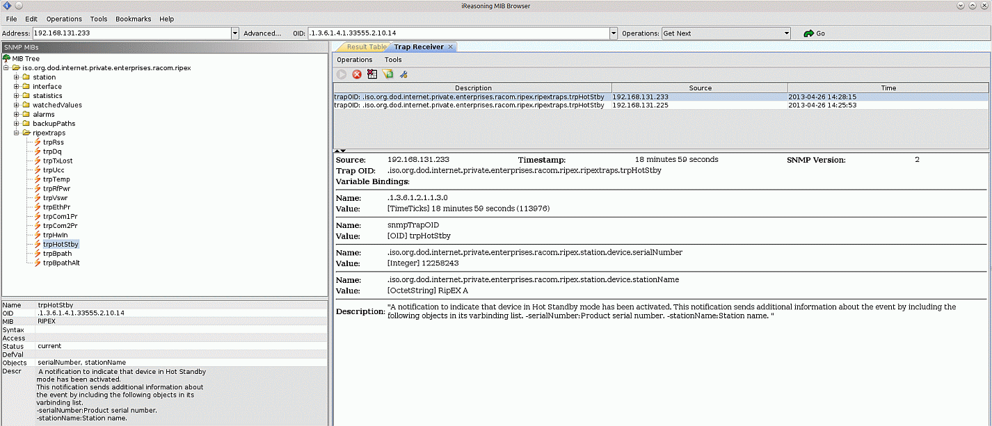
When SNMP trap information about switch-over to hot-stand-by RipEX unit is required, tick HS active SNMP alarm.
For more information about SNMP settings refer to RipEX User manual https://www.racom.eu/download/hw/ripex/free/eng/ripex-m-en.pdf

| Note | |
|---|---|
Since the units have got the same configurations ( same IP addresses), the unique identifier in SNMP trap is the “Unit name” (menu Settings/Device). It is recommended to set different names for A and B units (default RipEX A and RipEX B). |


