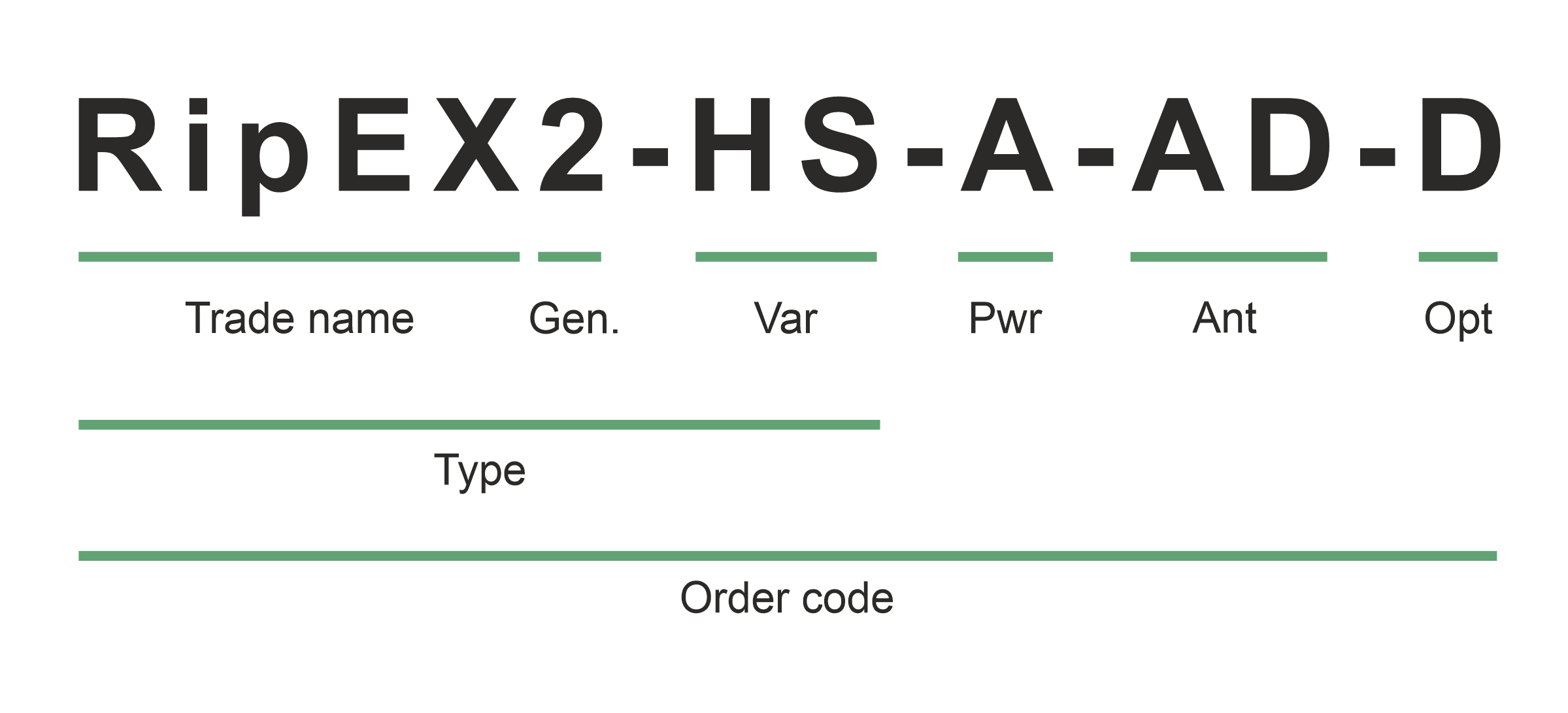
Trade name – trade and marketing name of the product. This name is used for all products within the same product family.
Possible values: RipEX
Gen – generation of the product of specific Trade name. The very first generation doesn’t have any number in this position.
Possible values: 2
Var – designation of product variant
Possible values:
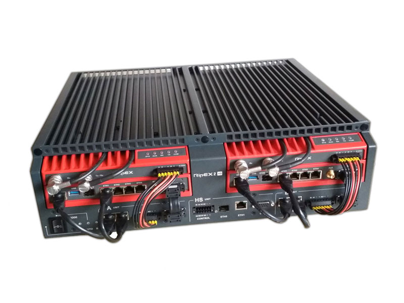
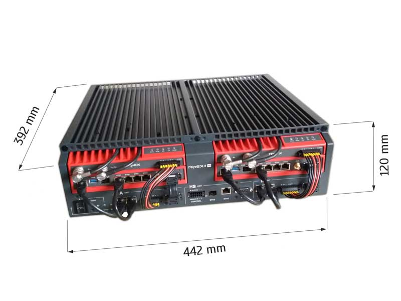
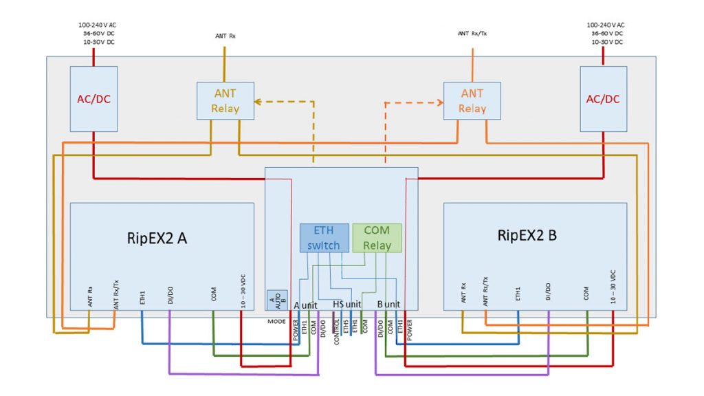
HS – 19″ chassis, Hot Standby controller, 2x pow.supply, for 2x RipEX2 (excl.)
RD – 19″ chassis, without controller, 2x pow.supply, for 2x RipEX2 (excl.)
RS – 19″ chassis, without controller, 1x pow.supply, for 1x RipEX2 (excl.)
Pwr – power input
Possible values:
A – 100-240 VAC, 50-60 Hz
D – 36-60 VDC, positive grounding possible
E – 10-30 VDC
F – 18-30 VDC, positive grounding possible
Ant – First letter – Radio interface antenna connectors
Possible values:
A – Var. HS: 1× N-female (Tx/Rx) – antenna switched for A and B unit
B – Var. HS: 2× N-female (Tx/Rx, Rx) – antennas switched for A and B unit
D – Var. HS or RD: 4× N-female (Tx/Rx, Rx; Tx/Rx, Rx) – no antenna switch, separate antennas for A and B unit
E – Var. RS: 2× N-female (Tx/Rx, Rx)
Ant – Second letter (optional) – Extension module antenna connectors
Possible values:
C – 2x SMA-female (ANT1; ANT1), no antenna switch
D – 4x SMA-female (ANT1, ANT2; ANT1, ANT2), no antenna switch
Opt – designation of internal option, if it is used
Possible values:
none
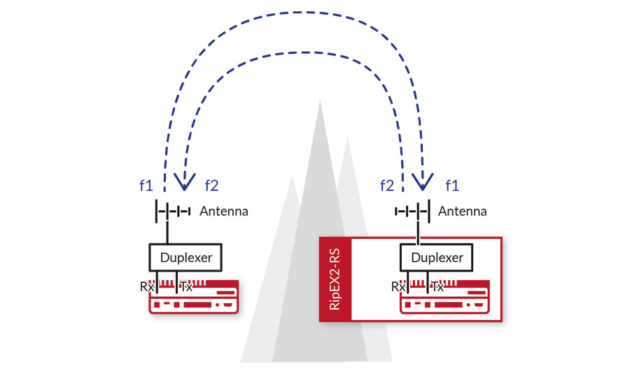
D – 1x internal duplexer, frequency details should be specified, for Var. RS + Ant. E or Var. HS + Ant. B
Type – specific product type for which type approvals like CE, FCC etc. are issued
Possible values:
RipEX2-HS (RipEX2-RD, RipEX2-RS in Code)
Order code – printed on Product label on the housing and used on Quotations, Invoices, Delivery notes etc.


